Indicated in figure 4 – Zilog S3F8S19 User Manual
Page 8
UM026801-0914
Establish a Connection with the PC
S3F8S19 Development Kit
User Manual
5
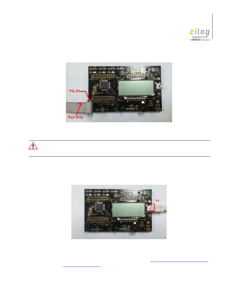
Ensure that you connect the 10 pin ribbon cable using the correct orientation to prevent
damage to the S3 Flash ISP.
5. With the USB A (male) to Mini-B cable, connect Port P1 on the S3F8S19 Develop-
ment Board to a USB port on the Development PC to apply power to the Development
Board, as indicated in Figure 5.
6. Install the Virtual COM port driver as described in
Appendix C. Install the USB Vir-
Figure 4. Debug Connector J6
Figure 5. Power Supply Port P1 Connector
Caution:
See also other documents in the category Zilog Sensors:
- S3F94C8 (11 pages)
- S3F80QB (29 pages)
- Z51F6412 (96 pages)
- Z51F6412 (54 pages)
- Z51F6412 (55 pages)
- Z16F6411 (216 pages)
- EZ80F93 (11 pages)
- Z16F6411 (20 pages)
- ZMOT0BSB (582 pages)
- EZ80F93 (13 pages)
- ZMOT0BSB (314 pages)
- Z8F083A (14 pages)
- Z8F082A (18 pages)
- Z8F2480 (17 pages)
- Z8F082A (15 pages)
- Z8F0822 (17 pages)
- Z8F6423 (83 pages)
- Z8F2480 (18 pages)
- Z8F2480 (19 pages)
- Z8F6423 (18 pages)
- Z8F6423 (27 pages)
- Z8F6482 (50 pages)
- EZ80L92 (26 pages)
- EZ80L92 (79 pages)
- EZ80F91GA (469 pages)
- EZ80F915 (411 pages)
- EZ80F91NAA (34 pages)
- EZ80F91 (41 pages)
- EZ80L92 (40 pages)
- EZ80L92 (10 pages)
- eZ80F92 (87 pages)
- Z16FMC6 (41 pages)
- ZUSBOPTS (38 pages)
- ZUSBOPTS (59 pages)
- Z16FMC6 (520 pages)
- Z8FMC16 (26 pages)
- Z16FMC6 (8 pages)
- Z16FMC6 (26 pages)
- ZMOT1AHH (25 pages)
- ZMOT0BSB (34 pages)
- EZ80F915 (78 pages)
- EZ80190 (87 pages)
- EZ80L92 (86 pages)
- EZ80F91GA (127 pages)