Theory of operation and specifications – Vectronics VEC-1320K User Manual
Page 35
VEC-1320K/1330K/1340K/1380K Owner's
Manual
33
may be replace by a small 1-A pigtail fuse or by a short length of #32 enameled
wire. Your kit will not power up until this is replaced.
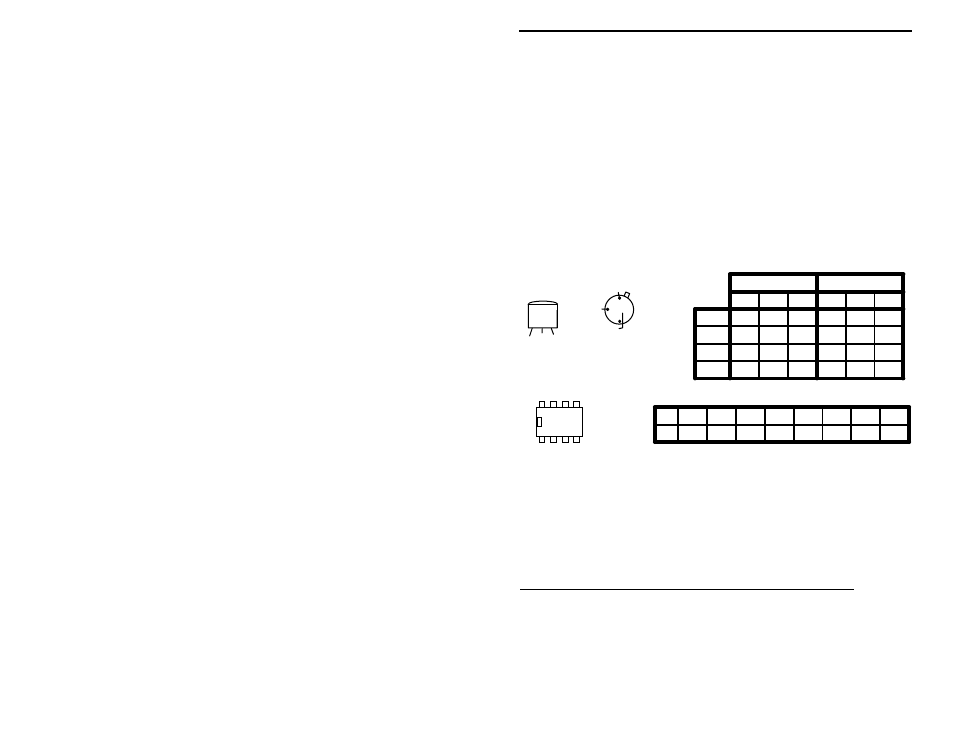
Voltage Analysis: Voltage analysis is a great way to pinpoint circuit problems.
To do this, you'll need a voltmeter or DVM. Clip the black lead (-) to ground
and use the red (+) probe to check the DC voltage at each IC or transistor lead.
Before making key-down transmitter readings, desolder and remove Y1 from the
pc board to prevent the transmitter from generating RF while you're attempting
to make DC voltage measurements. Receiver IC readings are made with the unit
in receive mode. Compare your readings against the chart below. They should
agree within 10-15%. If you observe one or more "bad" readings, this may
mean the device you're checking is blown--or that an incorrectly-installed part is
lurking near-by. Try using the schematic diagram to trace out the exact cause of
the problem.
E B C
E
B
C
(Collector is on Case)
(Emitter is grounded)
2N3053
Top View
2N3906-Q4
2N3904-Q1
PN2222-Q2
Front View
Q1
Q2
Q3
Q4
E
B
C
E
B
C
Standby
Key-Down
13.8
13.2
0
13.8
13.0
13.6
0
0
13.8
0
.7
7.7
0
0
13.8
0
0
13.8
0
0
0
5.7
6.3
12.6
VOLTAGE CHART
Q3
U1
U2
1
2
3
4
5
6
7
8
Pin
1 2 3 4
8 7 6 5
U1/U2
1.4
1.4
0
4.7
4.7
5.9
6.0
5.2
1.4
.02
.01
0
6.7
13.8
7.0
1.4
NE602
LM386
Important Note: Unit must not
generate RF during these checks!
If these checks fail to uncover the problem, repeat the "QC" check one more
time. Service records show that, for most malfunctioning kits, outright
component failure is relatively rare. In most cases, the culprit is a misplaced
part, reverse-polarized capacitor or diode, improperly installed transistor, or a
faulty solder connection! If, despite your best effort, you cannot solve a problem
with your radio, kit repair services are available through Vectronics. See the
warranty on the inside front cover for complete instructions.
THEORY OF OPERATION AND SPECIFICATIONS
The transceiver consists of a simple direct-conversion receiver and a three-stage
CW transmitter. Operating frequency is controlled by VXO (variable crystal
oscillator) Q1. Q1 is keyed on and off during transmit mode by dc-switch Q4.
During receive, it operates at reduced voltage which reduces mixer drive and