Vectronics VEC-1320K User Manual
Page 12
VEC-1320K/1330K/1340K/1380K Owner's
Manual
10
STEP-BY-STEP ASSEMBLY
Your transceiver kit will be constructed in three stages. First, you'll install the
smaller generic parts (resistors, capacitors, etc.) that are common to all four
models. Next, you'll mount frequency-determining components--those parts that
determine the specific band of operation for your particular kit. Finally, you'll
complete the project by installing larger generic parts such as jacks and
switches--things that might get in the way if installed first.
In these instructions, when you see the term install, this means to locate, identify,
and insert the part into its mounting holes on the pc board. This includes pre-
bending or straightening leads as needed so force is not required to seat the part.
Once a component is mounted, bend each lead over to hold it in place. Use
sharp side-cutters to clip off excess lead length before soldering. Make sure
trimmed leads don't touch other pads and tracks, or a short circuit may result:
Good
Not Good
The term solder means to solder the part's leads in place, and to inspect both (or
all) solder connections for flaws or solder bridges. Nip off excess protruding
leads with a sharp pair of side cutters.
Notice the directions use two sets of check boxes. Check one when a step is
complete and use the other for double-checking your work before operation.
Stage 1: Small Generic Parts
This kit contains 13 fixed-value 1/4 watt resistors. Begin construction by
mounting these first, starting with the smallest value and moving to the largest.
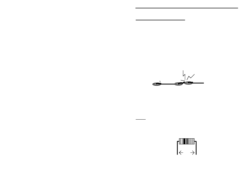
Before installing each one, carefully bend both leads to form right-angles, as
shown below:
.4"
When installing resistors, save a few of the clipped-off lead ends--you'll need
these for pc board jumpers later on.
Find two (2) 100 ohm resistors (brown-black-brown).