Vectronics VEC-1292K User Manual
Page 9
VEC-1292K Owner’s Manual
Stereo Transmitter Kit
9
! ! 25. Install a 1N4148 at D3 and solder.
There are three small trimpots in your kit. Find the two (2) 1K trimpots (marked
102).
When installing these, make sure they remain seated firmly against the board
during soldering.
! ! 26. Install a 1K pot (102) R2 and solder.
! ! 27. Install a 1K pot (102) R3 and solder.
! ! 28. Find the remaining 100K trimpot (marked 104). Install at R1 and
solder.
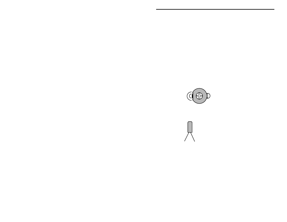
! ! 29. Find the 50 pF trimcap (orange, screwdriver adjust). Install at C12
with the flat side toward L1 and solder.
Trimcap
Install with the
"round to ground"
Locate the 38 kHz crystal. This is a small metal tube-shaped package with two
leads protruding from one end.
38 kHz digital watch crystal
! ! 30. Install the 38 kHz crystal at Y1.
Locate the .089 uH slug-tuned coil (red plastic coil form, metal shield can).
Before installing, make sure the coil's two pins and shield-can tabs are straight.
! ! 31. Position the .089 uH coil over the silkscreen legend for L3 and insert
carefully. Bend the two shield-can tabs over and solder in place.
Solder the two wire pins in place.
! ! 32. Find the 1 uH molded choke (brown-black-gold-silver). Install at L2
and solder.
The transmitter's output coil, L1, is a small 5-turn air-wound inductor. Use a 10-
32 screw shaft to make this coil. Ensure there are five complete turns on the
coil. After forming the coil, position as shown in the following: