Vectronics VEC-1292K User Manual
Page 7
VEC-1292K Owner’s Manual
Stereo Transmitter Kit
7
! ! 1. Find a 470 ohm resistor (yellow-violet-brown). Install at R8 and
solder.
! ! 2. Find a 4.7K ohm resistor (yellow-violet-red). Install at R6 and solder.
Locate the two 75K ohm resistors (violet-green-orange).
! ! 3. Install a 75K at R4 and solder.
! ! 4. Install a 75K at R5 and solder.
! ! 5. Find the 150K ohm resistor (brown-green-yellow). Install at R7.
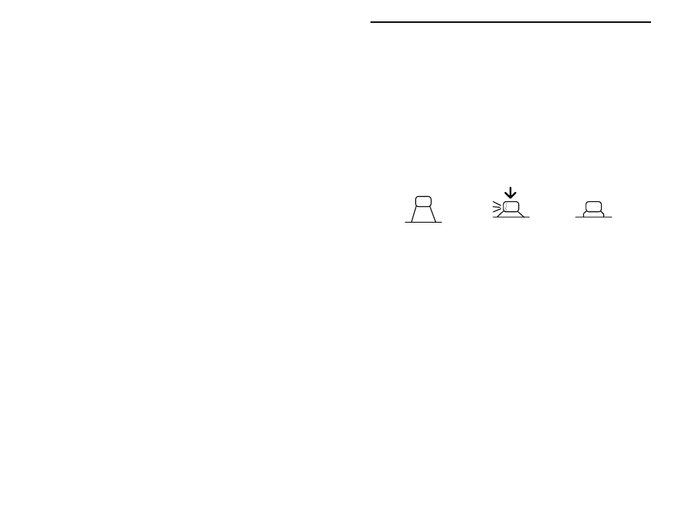
Next, install the kit's 12 multilayer capacitors. Avoid using force or excessive
heat when installing these. If the spacing isn't right, pre-form leads to the correct
spacing before inserting into the PC board.
Incorrect
Ooops!
Correct
Locate two (2) 10 pF multilayer capacitors (marked 10 or 100).
! ! 6. Install a 10 pF at C13.
! ! 7. Install a 10 pF at C14.
Locate two (2) 15 pF multilayer capacitors (15 or 150).
! ! 8. Install a 15 pF at C15.
! ! 9. Install a 15 pF at C16.
The next capacitor determines the frequency-tuning range of your FM
transmitter. For the low end of the band, or 88-94 MHz, find the 33 pF capacitor
(33 or 330). For the middle portion of the band, or 95-102 MHz, find the 27 pF
capacitor (27 or 270). For 102 MHz and up, use the 22 pF capacitor (22 or
220).
! ! 10. Install the capacitor you've selected at C18 and solder.
! ! 11. Find a 220 pF multilayer capacitor (221). Install at C17 and solder.
Locate six (6) .001 uF multilayer capacitors (102).
! ! 12. Install a .001 uF at C6 and solder.
! ! 13. Install a .001 uF at C7 and solder.
! ! 14. Install a .001 uF at C8 and solder.