Vectronics VEC-1292K User Manual
Page 8
VEC-1292K Owner’s Manual
Stereo Transmitter Kit
8
! ! 15. Install a .001 uF at C9 and solder.
! ! 16. Install a .001 uF at C10 and solder.
! ! 17. Install a .001 uF at C11 and solder.
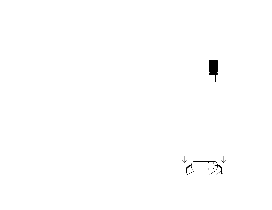
The last 5 fixed-value capacitors in your kit are electrolytic. Electrolytic caps
are polarized and must be installed the correct way in order to work. Each
capacitor's plus (+) mounting hole is marked on both the circuit board and parts
placement diagram. If the markings on the capacitor body are unclear, the plus
(+) lead is always the longer of the two.
+
Plus Lead
Locate the two (2) 10 uF electrolytic capacitors.
! ! 18. Install a 10 uF at C3 and solder.
! ! 19. Install a 10 uF at C4 and solder.
Locate the two (2) 22 uF electrolytic capacitors.
! ! 20. Install a 22 uF at C1 and solder.
! ! 21. Install a 22 uF at C2 and solder.
! ! 22. Find the 100 uF electrolytic capacitor. Install at C5 and solder.
This completes fixed capacitor installation. Before moving on, check each
electrolytic for correct polarity.
Locate the three (3) 1N4148 diodes (glass body). Like electrolytics, diodes are
polarized devices that must be installed correctly. Always look for the banded
end when installing.
! ! 23. Install a 1N4148 at D1 and solder.
! ! 24. Install a 1N4148 at D2 and solder.