Vectronics VEC-1292K User Manual
Page 10
VEC-1292K Owner’s Manual
Stereo Transmitter Kit
10
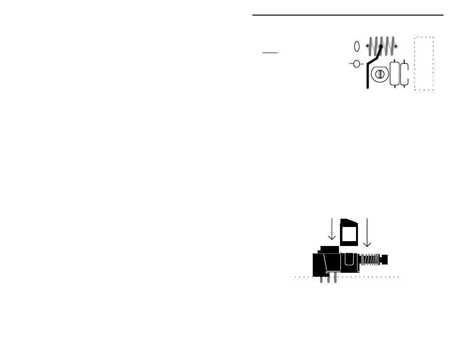
L2 R8
SW1
Y1
C12
L1
Antenna Lead
Separate the turns
two mounting holes.
Note:
evenly so the coil
fits between the
! ! 33. Install the 5-turn coil at L1 and solder.
L1 requires the addition of a center tap. If your coil has enamel insulation,
locate the center turn and scrape a patch of insulation off with a hobby knife to
expose the copper beneath. If the coil has tin plating, disregard this instruction
and solder directly to the plating.
! ! 34. Get the 2" length of insulated wire and strip 1/4" of insulation from
both ends (if necessary).
! ! 35. Tack-solder one end of the insulated wire to the middle turn of L1.
! ! 36. Place the other end of the insulated into W1 and solder.
Your kit contains a miniature DPDT switch. Some versions require installation
of a plastic clip-on support at the front of the switch body. This piece relieves
stress on the pins and ensures level seating. If your parts kit contains this piece,
install as shown:
Once the switch is prepared for installation:
! ! 37. Install the DPDT mini power switch at SW1
The Stereo Transmitter ICs in your kit will be installed using a IC socket. Like
the IC itself, the socket is keyed at one end to indicate proper positioning.