NEXCOM NEX 732L2G User Manual
Page 67
66
Appendix B
NEX732L2G User Manual
Logical Device 7
CRF0 (GPIO-GP17 I/O selection register)
When set to a ‘1’, the respective GPIO port is programmed as an input port.
When set to a ‘0’, the respective GPIO port is programmed as an output port.
CRF1 (GP10-GP17 data register)
If a port is programmed to be an output port, its respective bit can be read/written.
If a port is programmed to be an input port, its respective bit can only be read.
CRF2 (GP10-GP17 inversion register)
When set to a ‘1’, the incoming/outgoing port value is inverted.
When set to a ‘0’, the incoming/outgoing port value is the same as in the data
register.
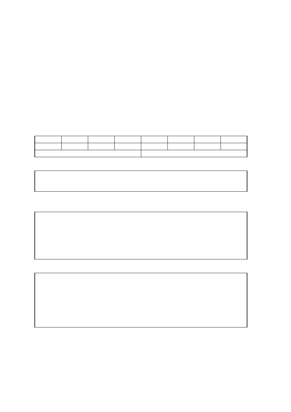
GP10-GP17
Bit7
Bit6
Bit5
Bit4
Bit3
Bit2
Bit1
Bit0
17
16
15
14
13
12
11
10
Output
Input
Ex
SIO_PORT
EQU
02EH
SIO_ENTRY
EQU
087H
SIO_EXIT
EQU
0AAH
SIO Entry Configuration Procedure
mov
dx, SIO_PORT
mov
al, SIO_ENTRY
out
dx,al
nop
nop
out
dx,al
Logical Device 7
mov
dx, SIO_PORT
mov
al, 07h
out
dx,al
;point to logical device number register
;
mov
al,07h
inc
dl
out
dx,al
;select logical device 7