Wiring outputs, Schematic diagram of si5580 output circuit plc, Si5580 – Applied Motion Si5580 User Manual
Page 15
-15-
Wiring Outputs
Before we discuss the output conditions, we need to talk about the circuitry. All three Si5580 outputs
are optically isolated. That means that there is no electrical connection between the indexer-drive and
the output terminals. The signal is transmitted to the output as light. What you “see” is a transistor
(NPN type) that closes, or conducts current, when the output is “low”. When the output is high, the
transistor is open.
Note: At power-up, the Si5580 sets all three programmable outputs high (open circuit).
Since there is no electrical connection to the Si5580, you must provide the source of current and
voltage, typically from a power supply. You must also limit the current to less than 100 mA so that the
output transistor is not damaged. You would normally use a resistor for this, but some loads (such as
PLC inputs) limit the current automatically.
The diagram below shows how to connect an Si5580 output to an optically isolated PLC input.
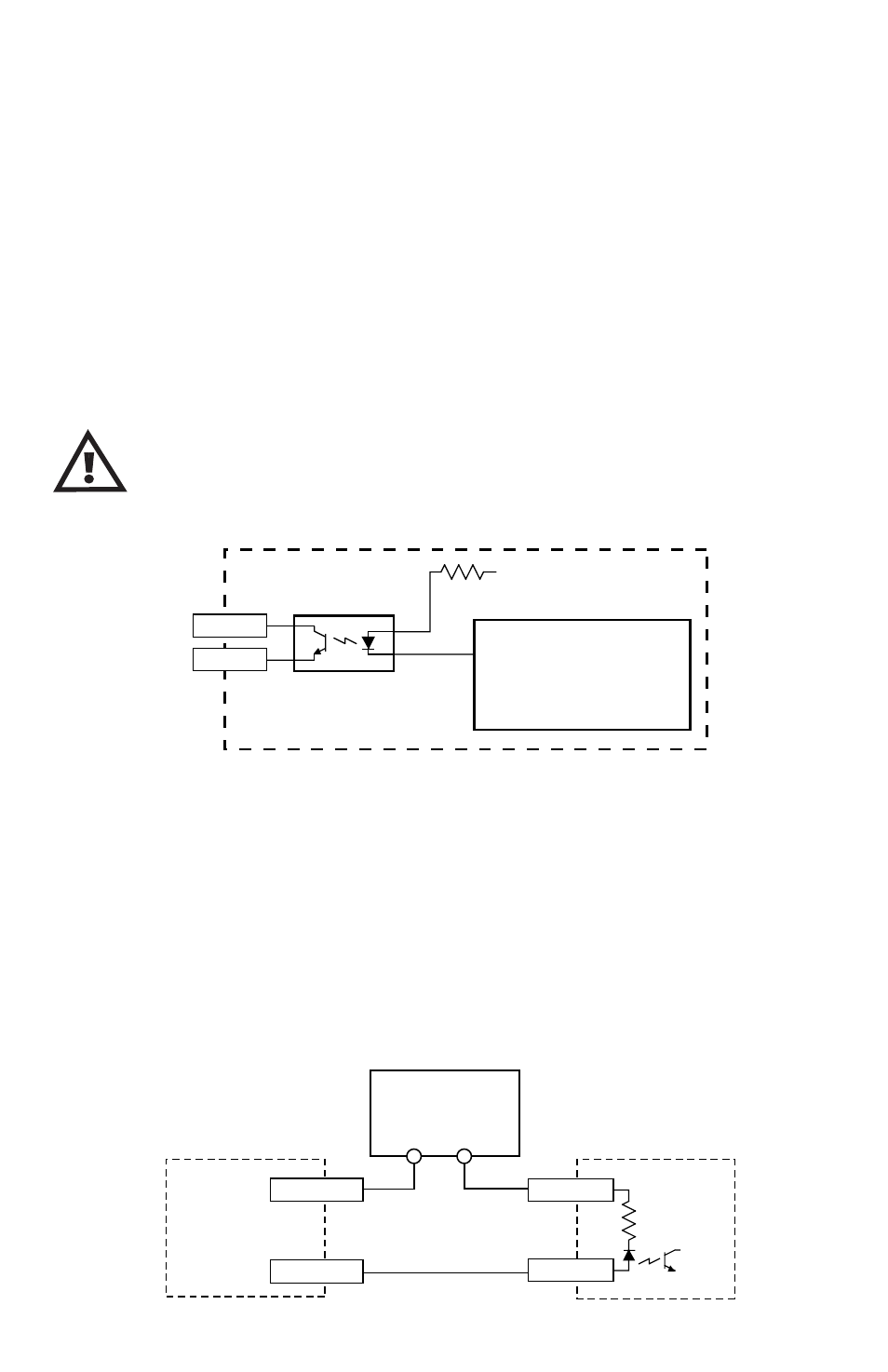
Schematic Diagram of Si5580 Output Circuit
PLC
COMMON
INPUT
Si5580
OUTPUT-
OUTPUT+
12-24 VDC
Power Supply
+
–
330W
+5V
OUT1–
OUT1+
Si5580
Controller Chip
inside Si5580
The maximum voltage between any pair of + and - output terminals is 24
volts DC. Never connect AC voltages to the Si5580 output terminals. Maxi-
mum current is 100 mA per output.