Configuration – ABUS Technologies A9696 Series Universal Controller User Manual
Page 9
ABUS TECHNOLOGIES INC.
9
A9696
7. CONFIGURATION
7.1 Programming the Indicator
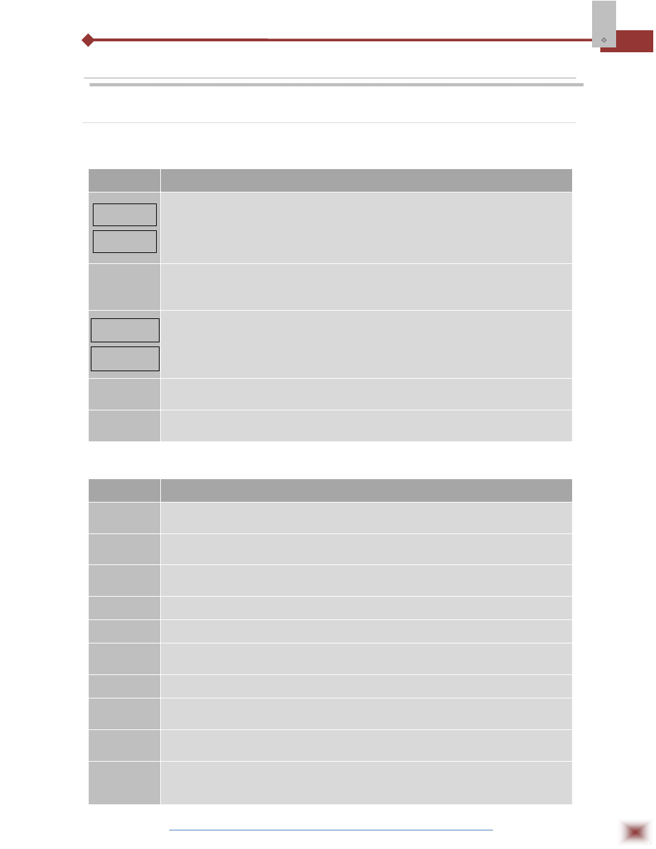
7.1.1 Operation Cycle
PARAMETER
PROMPT PARAMETER DESCRIPTION
PV Indication
(Red)
SV Indication
(Green)
PV AND SV INDICATION: The status display shows the present value of PV
(Process Variable). The parameter display shows SV (Set Variable).
The status display shows “- - - -“whenever PV exceeds the maximum range or
there is no signal at the input. In case of hardware error the status display will show
Ern, where n is the error code.
avto
CONTROL MODE: YES indicates automatic control mode (closed loop, PID or
ON/OFF). NO indicates manual control mode (open loop). Bumpless transfer from
auto to manual mode is available. If in doubt program YES.
PV Indication
(Red)
MV Indication
(Green)
MANIPULATED VARIABLE VALUE (MV): The upper display shows PV value and
the lower display shows the percentage of MV applied to the control output. When
in manual control the MV value can be manually changed. When in auto mode the
MV value can only be viewed. To distinguish the MV display from the SV display,
the MV is shown flashing intermittently.
Pr n
RAMP AND SOAK PROGRAM SELECTION: Selects the ramp and soak program
to be executed (7 programs possible).
rvn
CONTROL ENABLE: YES means that the control output and alarms are enabled
and NO means they are disabled.
7.1.2 Auto Tuning Cycle
PARAMETER
PROMPT PARAMETER DESCRIPTION
atvn
AUTO-TUNE: YES enables the auto tuning of the PID parameters and NO disables
it.
Pb
PROPORTIONAL BAND: Percentage of maximum input span. Select zero for
ON/OFF control.
xyst
CONTROL HYSTERESIS (in engineering units): This parameter is only shown for
ON/OFF control (Pb=0).
‘ ir‘
INTEGRAL RATE: Integral time constant in repetitions per minute (Reset).
dt
DERIVATIVE TIME: Derivative time constant, in seconds.
(t
CYCLE TIME: PWM period in seconds. Can only be viewed if proportional band is
other than zero.
bias
Offset for MV (manual reset). Range: -100% to +100%. Default value: 0.
ovll
OUTPUT LOW LIMIT: minimum percentage value for MV (Manipulated Variable)
when in automatic control and PID. Default value: 0.0%
ovxl
OUTPUT HIGH LIMIT: Maximum percentage value for MV when in automatic
control and PID. Default value: 100.0%
sfst
SOFT START: Time in seconds during which the controller limits the MV value
progressively from 0 to 100%. It is enabled at power up or when the control output
is activated. If in doubt set zero.