ABUS Technologies A9696 Series Universal Controller User Manual
Page 8
ABUS TECHNOLOGIES INC.
8
A9696
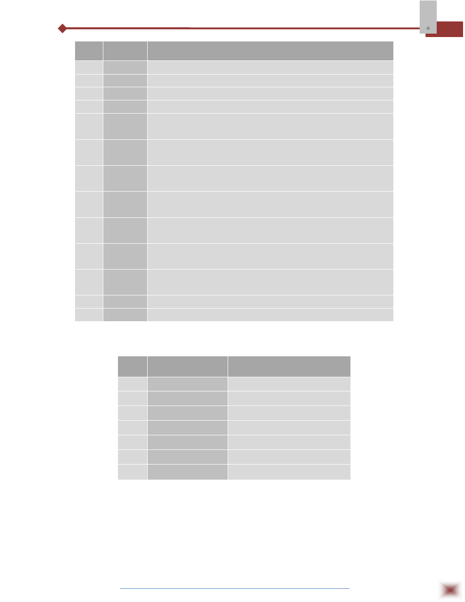
S.No. Parameters
Description
1
A1-A4
Show active alarms.
2
COM
Flashes when communication messages are sent by the controller.
3
TUNE
Lights during the execution of PID automatic tuning.
4
MAN
Lights when the controller is in manual.
5
RUN
Lights when the controller is active, with control and alarm outputs
enabled.
6
OUT
For relay or pulse control output, reflects the actual state of the output.
If an analog output is assigned for control, lights continuously.
7
P
Program Key: This key is used to access different displays with the
programmable parameters of the device.
8
◄
Back Key: This key is used to go back to the previous parameter
displayed in the menu cycle.
9
▲
UP / MAX Key: This key is used to increase parameter value, as well
as to display maximum values stored in memory.
10
▼
DOWN / MIN Key: This key is used to decrease parameter value, as
well as to display minimum values stored in memory.
11
F
This special function key is used for pre-programmed functions as
explained in the table below.
12
Display
Shows the Process Variable (PV) and the programming prompts.
13
Display
Shows the Set-Point Variable (SV) and the programming prompts.
Pre-Programmed Functions
S.NO.
CYCLE
ACCESS
1
Operation
Free access parameters *
2
Tuning
3
R&S Program
4
Alarms
Reserved access parameters **
5
Input Configuration
6
I/Os
7
Calibration
*
These parameters can be viewed but not changed if the cycle is protected.
**
Requires a key combination to access the cycle.