ABUS Technologies A9696 Series Universal Controller User Manual
Page 18
ABUS TECHNOLOGIES INC.
18
A9696
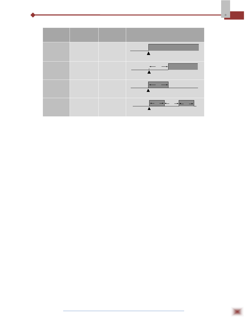
Advanced Timer Alarm (for alarms 1 or 2):
ALARM
FUNCTION
T1
T2
ACTION
Normal
0
0
Alarm Event
Alarm
Output
Delayed
0
1 s to 6500 s
Alarm Event
Alarm
Output
T2
Pulse
1 s to 6500 s
0
Alarm Event
Alarm
Output
T1
Oscillator
1 s to 6500 s
1 s to 6500 s
Alarm Event
Alarm
Output
alarme
T1
T2
T1
7.4.3 ALARM INITIAL BLOCKING
The initial blocking option inhibits the alarm from being recognized if an alarm condition is
present when the controller is first energized. The alarm will actuate only after the occurrence of a non-
alarm condition followed by a new occurrence for the alarm. The initial blocking is disabled for the
sensor break alarm function.
7.4.4 SQUARE ROOT EXTRACTION
Available when input type 19 is selected. The indicator displays the square root of the current
signal input applied to terminals.
7.4.5 REMOTE SET-POINT
The remote Set-point (SP) is enabled by an external digital signal in either I/O5 or I/O6, when
programmed with code 8 (Select remote SP input).
7.4.6 ANALOGUE RETRANSMISSION OF PV AND SP
The analog output, when not used for control purposes, is available for retransmitting the SV
and SP values in 0-20 or 4-20mA. This analog output is electrically isolated from other inputs and
outputs. The analog output signal is scalable, with the output range determined by the values
programmed in the parameters “SPLL” and “SPkL”. To obtain a voltage output, connect a resistor shunt
to the current output terminals.
7.4.7 SOFT START
Defines the time interval for the output to reach its maximum value (100%). The soft start value
is programmed in “SfSt”. See also parameters “ovLL” and “ovkL”.