Ordering details, Connections – ABUS Technologies A9696 Series Universal Controller User Manual
Page 6
ABUS TECHNOLOGIES INC.
6
A9696
4. ORDERING DETAILS
The basic unit includes one universal input, two SPST relays, two SPDT relays, 24Vdc
output for powering remote transmitters, one digital input, a 4-20 mA input for remote
set-point and one 4-20 mA output which can also be used as a digital input or output .
Option 1: RS485 digital communication interface with Modbus RTU protocol.
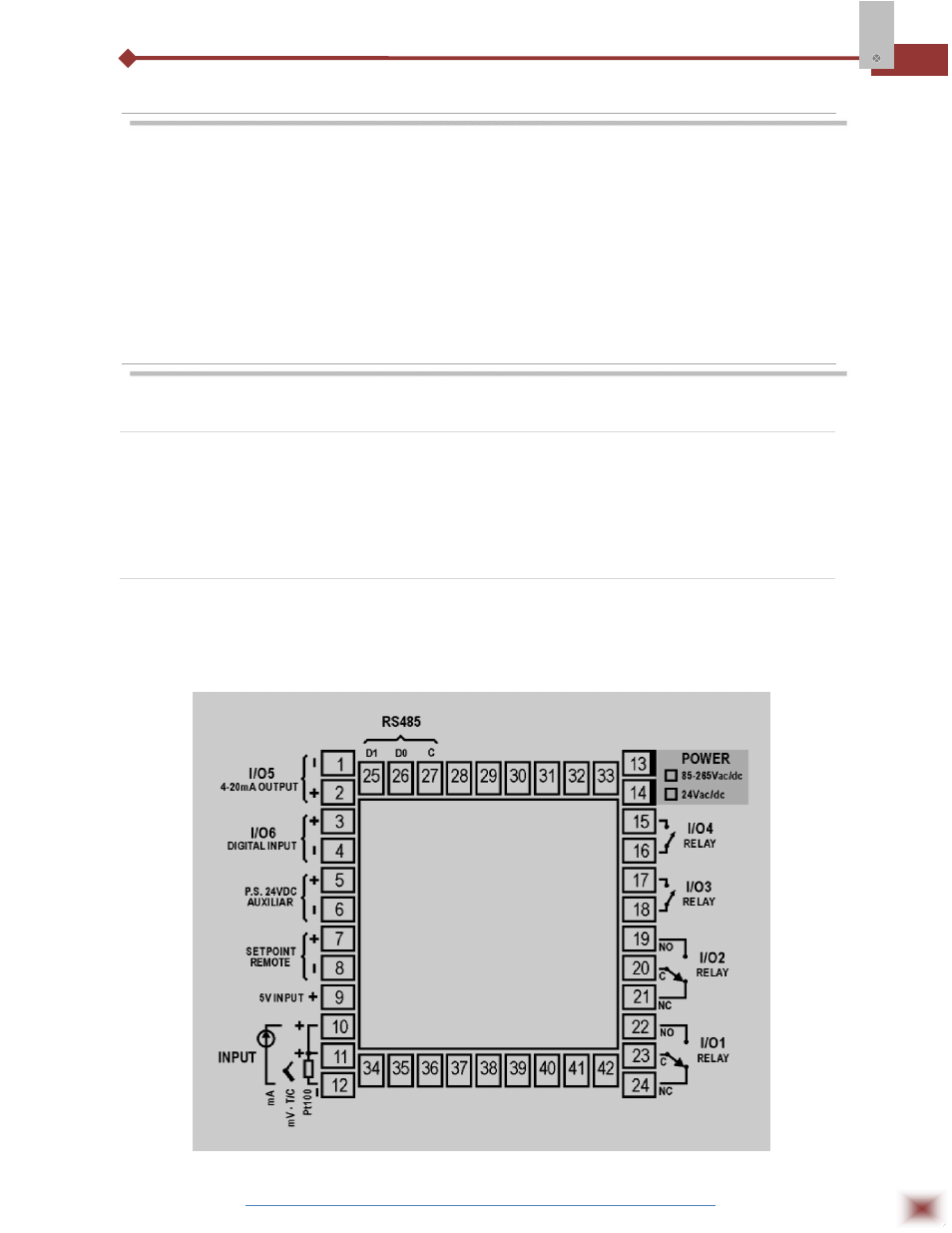
5. CONNECTIONS
5.1 Electrical Connections
All electrical connections are made to the screw terminals at the rear of the controller. They
accept wire sizes from 0.5 to 1.5 mm2 (16 to 22 AWG). The terminals should be tightened to a torque
of 0.4 Nm (3.5 lb in).
.
5.2 Routing of Wires
To minimize the pick-up of electrical noise, the low voltage DC connections and the sensor
input wiring should be routed away from high-current power conductors. If this is impractical, use
shielded cables. In general, keep cable lengths to a minimum.