ABUS Technologies A9696 Series Universal Controller User Manual
Page 10
ABUS TECHNOLOGIES INC.
10
A9696
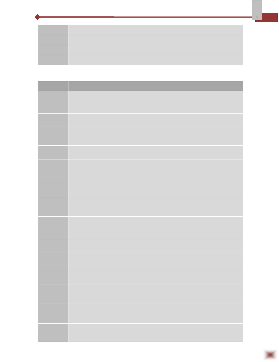
Sp.a1
ALARM 1 PRESET: Tripping point for alarm 1.
Sp.a2
ALARM 2 PRESET: Tripping point for alarm 2.
Sp.a3
ALARM 3 PRESET: Tripping point for alarm 3.
Sp.a4
ALARM 4 PRESET: Tripping point for alarm 4.
7.1.3 Ramp and Soak Profile Programming Cycle
PARAMETER
PROMPT PARAMETER DESCRIPTION
tbas
TIME BASE: Selects the time base for the ramp and soak. Valid for all profile
programs.
0
- PT1 to PT7 values are in seconds;
1
- PT1 to PT7 values are in minutes;
Pr n
PROGRAM TO BE VIEWED: Selects the ramp and soak profile program to be
edited/viewed in the following cycle prompts (7 programs available).
ptol
RAMP AND SOAK TOLERANCE: maximum deviation between PV and SV.
Whenever this deviation is exceeded the time counter is halted until deviation
lowers to within the tolerance. Set zero to disable this function.
Psp0
Psp7
RAMP AND SOAK SET POINTS (0 to 7): Set of 8 SV values which define the ramp
and soak profile segments. See also PT1 to 7 and PE1 to 7 below.
Pt1
Pt7
RAMP AND SOAK SEGMENTS TIME (1 to 7): Set of 7 time intervals for the 7
segments of the ramp and soak program. Up to 9999 seconds or minutes,
according to tbAS parameter.
Pe1
Pe7
RAMP AND SOAK EVENT (1 to 7): Set of 7 values that define which alarms must
be activated during a ramp and soak program segment.
Alarm function depends on “rS” setting (Table 7.4.2 ALARM FUNCTIONS).
lp
LINK TO PROGRAM: Number of the next profile program to be linked to follow the
current profile. Profiles can be linked to make larger programs of up to 49
segments.