Pin female plug signal names and programming modes, Circuit board header connection – Altera USB-Blaster II User Manual
Page 13
Chapter 2: USB-Blaster II Download Cable Specifications
2–3
10-Pin Female Plug Signal Names and Programming Modes
October 2014
Altera Corporation
USB-Blaster II Download Cable
User Guide
10-Pin Female Plug Signal Names and Programming Modes
Circuit Board Header Connection
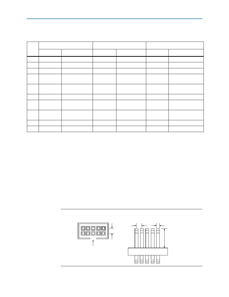
The 10-pin male header, which connects to the download cable's 10-pin female plug,
has two rows of five pins. The pins are connected to the device’s programming or
configuration pins.
c
If the header connection on the circuit board is a male receptacle, it must have a key
notch. Without a key notch, the 10-pin female plug will not connect. The following
figure shows a typical 10-pin male header with a key notch.
Table 2–2. 10-Pin II Female Plug Signal Names and Programming Modes
Pin
Active Serial (AS) Mode
Passive Serial (PS) Mode
JTAG Mode
Signal Name
Description
Signal Name
Description
Signal Name
Description
1
DCLK
Clock signal
DCLK
Clock signal
TCK
Clock signal
2
GND
Signal ground
GND
Signal ground
GND
Signal ground
3
CONF_DONE
Configuration done
CONF_DONE
Configuration done
TDO
Data from device
4
VCC(TRGT)
Target power supply
VCC(TRGT)
Target power
supply
VCC(TRGT)
Target power supply
5
nCONFIG
Configuration
control
nCONFIG
Configuration
control
TMS
JTAG state machine
control
6
nCE
Cyclone chip enable
—
No connect
PROC_RST
Hard processor reset
7
DATAOUT
Active serial data
out
nSTATUS
Configuration
status
—
No connect
8
nCS
Serial configuration
device chip select
—
No connect
—
No connect
9
ASDI
Active serial data in
DATA0
Data to device
TDI
Data to device
10
GND
Signal ground
GND
Signal ground
GND
Signal ground
Note to
(1) Use pin 6 for a hard processor reset under JTAG mode.
Figure 2–4. 10-Pin Male Header Dimensions - Inches and Millimeters
0.025 (0.635) Sq.
0.235 (5.969)
0.100
Side View
0.100 (2.540)
Top View
A key notch is required.