Nexen RSD100 964520 User Manual
Page 9
9
FORM NO. L-21107-H-0108
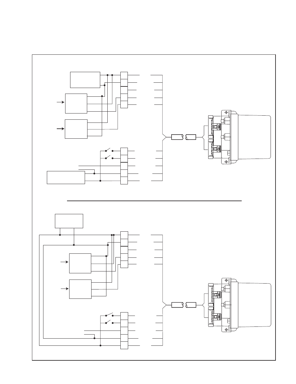
Figure a Wiring Diagram if using DPS0a or DPS0a
RSD100
PINK
ORANGE
YELLOW
PURPLE
GRAY
RED
BLACK
WHITE
GREEN
24V
Power Supply
+
_
Arm Position
Sensor
Signal
+24V
com
+_
Machine State
Boost
Control Output
RSD100
PINK
ORANGE
YELLOW
PURPLE
GRAY
RED
BLACK
WHITE
BROWN
GREEN
24V
Primary
Power Supply
+
_
Arm Position
Sensor
Signal
+24V
com
Second
Power Supply
+
_
+_
_
Machine State
Boost
Control Output
Nexen
Ultrasonic
Sensor
Roll Diameter
Sensor
+24V
Signal
com
Nexen
Ultrasonic
Sensor
Roll Diameter
Sensor
+24V
Signal
com
BROWN
Nexen
DPS30A
or
DPS60A
Nexen
DPS30A
or
DPS60A
external electrical Connections
Isolated Output
external electrical Connections
Non-Isolated Output
Verify which model of position sensor is being used.
For Nexen’s DPS30A or DPS60A, refer to Figure 4a.
For Nexen’s DPS30, DPS60 or mechanical potentiometer, refer to Figure 4b.
1.3 w
iRing
D
iAgRAmS