Nexen RSD100 964520 User Manual
Page 10
FORM NO. L-21107-H-0108
10
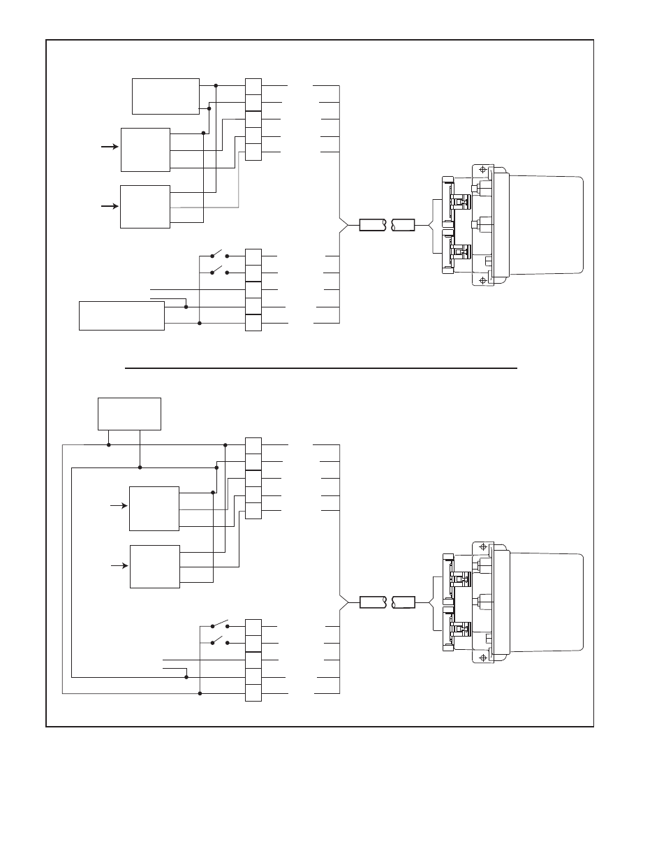
Figure b Wiring Diagram if using DPS0, DPS0 or a Mechanical Potentiometer
RSD100
PINK
ORANGE
YELLOW
PURPLE
GRAY
RED
BLACK
WHITE
GREEN
24V
Power Supply
+
_
Arm Position
Sensor
Signal
+12V
com
Nexen
DPS30,
DPS60
or
Mechanical
Potentiometer
+_
Machine State
Boost
Control Output
RSD100
PINK
ORANGE
YELLOW
PURPLE
GRAY
RED
BLACK
WHITE
BROWN
GREEN
24V
Primary
Power Supply
+
_
Arm Position
Sensor
Signal
+12V
com
Second
Power Supply
+
_
+_
_
Machine State
Boost
Control Output
Nexen
Ultrasonic
Sensor
Roll Diameter
Sensor
+24V
Signal
com
Nexen
Ultrasonic
Sensor
Roll Diameter
Sensor
+24V
Signal
com
BROWN
Nexen
DPS30,
DPS60
or
Mechanical
Potentiometer
external electrical Connections
Isolated Output
external electrical Connections
Non-Isolated Output
This manual is related to the following products: