Nexen RSD100 964520 User Manual
Page 13
1
FORM NO. L-21107-H-0108
1.6 J
umpeR
& S
witch
S
ettingS
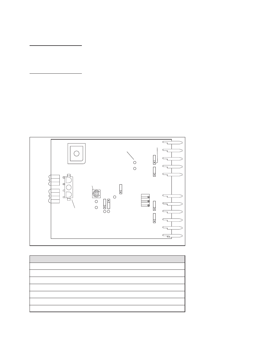
Make the appropriate Jumper and Switch Settings shown below for your application. The RSD100 printed circuit-
board can be removed to facilitate access to all jumpers and switches.
B
OARD
R
emOvAl
i
nStRuctiOnS
:
1. Remove power from RSD100.
2. Disconnect the Power and Signal Cable Connectors from the RSD100 base.
3. Move the printed circuit board side-to-side while pulling to remove board.
J
umpeR
AnD
S
witch
S
ettingS
: (R
efeR
to
f
iguRe
8.)
Figure
Table 1
n
o
it
a
n
g
i
s
e
D
r
o
l
o
C
n
o
it
c
n
u
F
1
I
n
e
e
r
G
t
n
e
s
e
r
p
s
i
C
D
V
5
+
n
e
h
w
N
O
"
2
I
n
e
e
r
G
t
n
e
s
e
r
p
s
i
C
D
V
2
1
+
n
e
h
w
"
N
O
"
3
I
d
e
R
e
r
u
s
s
e
r
p
ri
a
g
n
i
s
a
e
r
c
n
i
n
e
h
w
"
N
O
"
4
I
d
e
R
e
r
u
s
s
e
r
p
ri
a
g
n
i
s
a
e
r
c
e
d
n
e
h
w
"
N
O
"
5
I
w
o
ll
e
Y
t
u
p
n
I
t
s
o
o
B
o
t
d
e
il
p
p
a
s
i
e
g
a
tl
o
v
n
e
h
w
"
N
O
"
6
I
w
o
ll
e
Y
t
u
p
n
I
e
t
a
t
S
e
n
i
h
c
a
M
o
t
d
e
il
p
p
a
s
i
e
g
a
tl
o
v
n
e
h
w
"
N
O
"
7
I
w
o
ll
e
Y
l
o
r
t
n
o
c
l
a
u
n
a
m
n
i
n
e
h
w
"
N
O
"
Auxiliary
RS232 Port
Rotary
Switch
I6
I5
P3
P4
P5
Jumper
Indicator
12V
W4
10V
12V
W3
10V
R35
R38
R37
U4
DIG IN 2
W6
TX
DIG IN 1
W5
RX
I4
I3
I2
I7
I1
1
W2
2
U13
REV
W1
NORM
I OUT
W7
V OUT
Not Used
Optional
Pressure
Sensor
Connection
Red
Black
White
NORM, if controller action is backwards, then select REV
Position 1
10 V or 12 V, depends on maximum output voltage of sensor, use
10 V for Nexen’s DPS 30A or DPS 60A sensor, and 12V for mechanical potentiometer.
10 V, for Nexen’s Roll Diameter Sensor
Dig. In 1, if using this input for Machine State Signal
Rx, if using this input for RS232 communication
Dig. In 2, if using this input for Boost Signal
Tx, if using this input for RS232 communication
V Out, for 0 – 10 VDC analog output
I Out, for 4 – 20 mA analog output
Refer to Table 2
Jumper W1
Jumper W2
Jumper W3
Jumper W4
Jumper W5
Jumper W6
Jumper W7
Rotary Switch
After completing all jumper and switch settings: replace printed circuit board, reconnect connectors and apply 24 VDC
power. Next, check that both green Indicators, I1 and I2, are on. If not, refer to the TROUBLESHOOTING section.
Otherwise, connect the RSD Communications Software cable to the Auxiliary RS232 Port and a computer. Refer to
the RSD Communications Software Installation and Connection Manual for instructions how to use the program.