Nexen RSD100 964520 User Manual
Page 8
FORM NO. L-21107-H-0108
+ VDC & DC Common: The RSD100 requires 24
VDC to operate (Refer to the SPECIFICATIONS section
for current rating.).
Sensor excitation: This output provides +12 VDC
as an excitation voltage for dancer arm position
sensors such as Nexen’s older DPS 30 or DPS 60
sensors and mechanical potentiometers (Refer to the
SPECIFICATIONS section for current rating.) If using
Nexen’s DPS30A or DPS60A sensors, note that the
excitation voltage required is + 24 VDC.
Position Sensor Input: The position sensor input is
a 0–10 or 0–12 VDC signal that is provided from the
dancer arm position sensor. The choice of voltage range
is selected by Jumper W3 (Refer to Figure 8). For best
results the voltage range should match the dancer arm
swing (i.e.: a 30° dancer arm swing should produce nearly
a 0–10 VDC or 0–12 VDC position signal).
Roll Diameter Sensor Input: This input accepts an
optional 0 – 10 VDC signal that represents roll diameters
from maximum full roll to core (refer to Section 6.0B).
Machine State Signal or RS Receive: This input
has two functions: first, to accept a Machine State
Signal; and second, to act as the receive line for RS232
communications. The function is chosen by Jumper W5
(Refer to Figure 8).
As a Machine State input, this signal uses Isolated DC
Common as a return. When 12-24 VDC is applied, the
controller will respond according to how this input was
setup (refer to Machine State Signal selection in Section
1.5). This feature tells the RSD100 controller when the
machine starts and stops. A yellow indicator, I6, on the
controller’s printed circuit board will be on when 12-24
VDC is present at this input.
As the receive line (Rx) for RS232 communications,
this input, the next input (Tx), and DC Common are
all that is needed to communicate with the RSD100
(Refer to Figure 5.). Communications setup broadcast
and command parameters can be sent back and forth
between the controller and other devices such as a
PLC or computer by using RS232 . When using this
input as the receive line for RS232 communications, the
Machine State Signal command has to be sent via this
communications link.
boost or RS Send: This input has two functions:
first, to accept the Boost signal; and second, to act as
the send line for RS232 communications. The function is
chosen by jumper W6 (Refer to Figure 8).
As the Boost input, this signal uses the Isolated DC
Common as a return. When 12-24 VDC is applied
momentarily, the controller will respond by applying
Boost Multipliers to the controller gains (refer to Section
11). This feature is used to increase the responsiveness
of the RSD100 during events such as machine
acceleration and deceleration. Otherwise, when no
signal is present, the controller will operate normally. A
yellow indicator, I5, on the controller’s circuit board will
be on when 12-24 VDC is present at this input.
As the send line (Tx) for RS232 communications, this
input, the previous input (Rx), and DC common are
all that is needed to communicate with the RSD100
(Refer to Figure 5.). Communications setup broadcast
and command parameters can be sent back and forth
between the controller and other devices such as a PLC
or computer by using RS232. When using this input
as the send line for RS232 communications, the Boost
command has to be sent via this communications link.
Control Signal Output: This output signal can be used
as an input to a current or voltage-to-pressure transducer
or as a trim signal to a motor drive. The output is chosen
by jumper W7 (Refer to Figure 8). The output can be
set to 0–10 VDC or 4–20 mA. Both ranges are already
calibrated and ready for use.
Isolated DC Common Input: In cases where isolated
Machine State and Boost inputs or Analog Signal Output
is desired, this input is the return line for the isolated
power supply (supplied by user). If isolation is not
needed, this input must be connected to DC Common
input.
Isolated + VDC Input: In cases where isolated
Machine State and Boost inputs or Analog Signal Output
is desired, this input is the supply line for the isolated
15-24 VDC power supply (supplied by user). If isolation
is not needed, this input must be connected to the +24
VDC input.
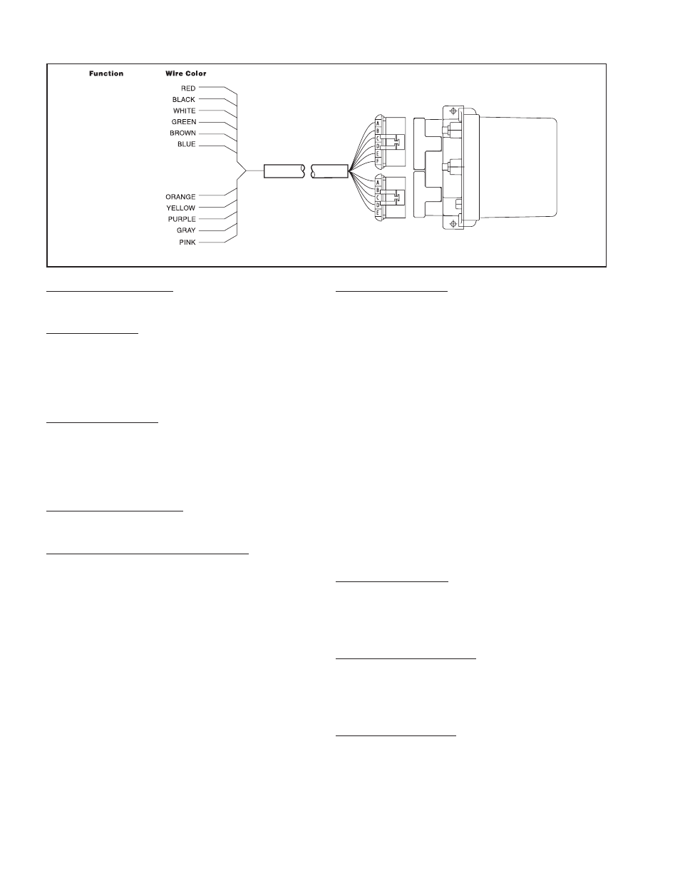
Figure
RSD100 electrical Connections
Sensor Excitation
+24 VDC
DC Common
Position Sensor Input
Not Used
Roll Dia. Sensor Input
Machine State, Rx
Isolated DC Common Input
Control Signal Output
Boost, Tx
Isolated Input
RSD100
1.2 e
lectRicAl
c
OnnectiOnS