Rsd100 s – Nexen RSD100 964520 User Manual
Page 6
FORM NO. L-21107-H-0108
RSD100 S
etup
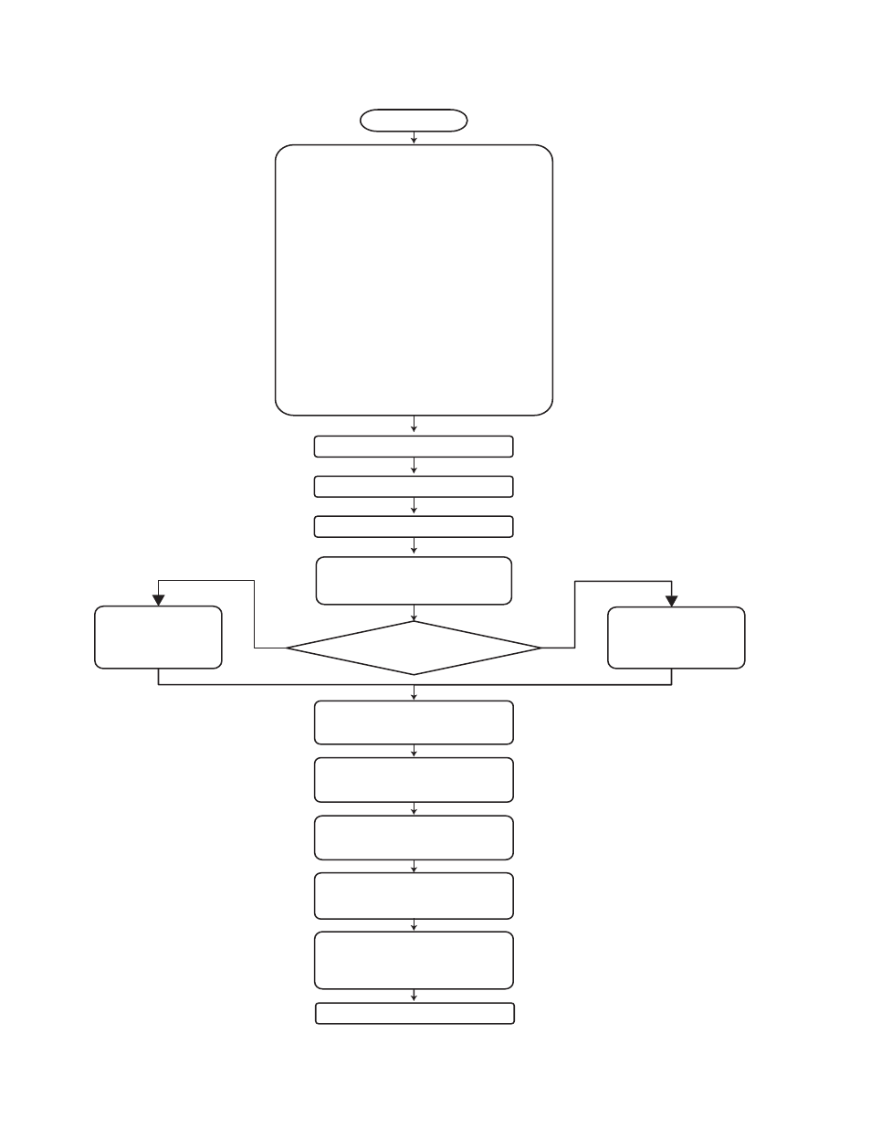
The following flowchart outlines the RSD100 setup.
2.0 Dancer Range Calibration
4.0 Units
1.0 Installation / Connections
1.1 Installation
1.2 Electrical Connections
+24 VDC & DC Common
Sensor Excitation
Position Sensor Input
Roll Diameter Sensor Input
Machine State Signal or RS232 Receive
Boost or RS232 Send
Control Signal Output
Isolated DC Common
Isolated +24 VDC
1.3 Roll Diameter Sensor
1.4 RSD100P Pneumatic Connections
Current or Voltage-to-Pressure Transducer
Tension Setpoint Sensor
Switch & Jumper Settings
Board Removal Instructions
1.5 Jumper & Switch Settings
Machine State Signal Selection
3.0 Manual Control of OUTPUT
5.0 Tension Compensation
Low Tension
High Tension
6.0A OBA Settings
Diameter Ratio
Full Roll Output
Core Output
6.0B DBA Settings
Core Diameter
Full Roll Diameter
Start
6.0
Roll Diameter Sensor Used?
7.0 Output Limits
Minimum
Maximum
8.0 Stopped Settings
Bleed Rate
Output
9.0 Gains/Tuning
Gain
Adaptive Slope
10.0 Start Settings
Duration
Multiplier
11.0 Boost Settings
Duration
Proportional Multiplier
Derivative Multiplier
12.0 Dancer Setpoint
no
yes