Nexen RSD100 964520 User Manual
Page 12
FORM NO. L-21107-H-0108
1
1.5 RDS100p p
neumAtic
c
OnnectiOnS
Nexen developed the RSD100P for applications that would benefit from tension setpoint compensation (as
determined by the RSD100 Applications Chart). The RSD100P features an integral pressure sensor that connects
to the air supply pressure of the dancer arm loading cylinder. As the tension setpoint changes via the air pressure of
the loading cylinder, the RSD100P measures this change and adjusts its performance accordingly. The RSD100P
pressure sensor’s calibration procedure is listed in the Tension Compensation portion of Section 5.
RSD100P
Brake,
Clutch,
or Drive
Control
Output
Signal
Pneumatic
Loading
Cylinder
User Supplied
Air Pressure
Current or Voltage-to-Pressure Transducer
Tension
Setting Air
Pressure
Regulator
Figure
1.4 R
Oll
D
iAmeteR
S
enSOR
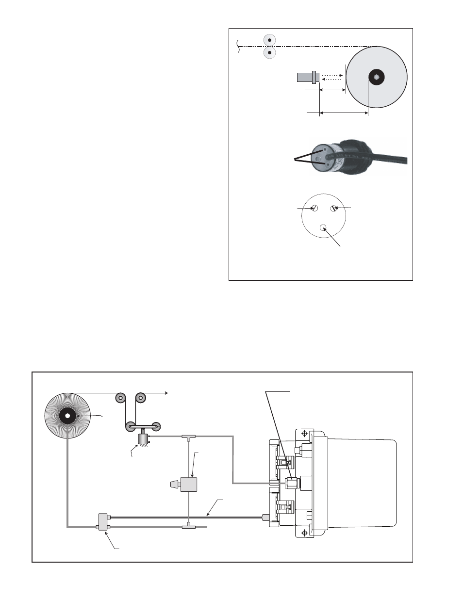
An Ultrasonic Sensor can measure the change in roll radius
by bouncing sound waves off the material, enabling the
RSD100 to calculate roll diameter. For calibrations to be
accurate, the sensor must be installed perpendicular to
the axis of the wind or unwind shaft. Also, the Ultrasonic
Sensor must be mounted at least four inches [100 mm]
away from the maximum diameter roll.
adjustment of the Ultrasonic Sensor
Nexen’s Ultrasonic Sensor is factory adjusted for a 4 to 40
inch range and typically does not require re-adjustment prior
to use. If a shorter range is desired, then re-adjustment may
be performed by connecting a voltmeter to the sensor’s
output and turning P1 for the near point adjustment and P2
for the far point adjustment. (See figure 6) Adjust P1 and
P2 until the output voltage covers as much of the 0 to 10
VDC range as possible over the desired distance.
NOTe: The indicator on the end of the Ultrasonic
Sensor provides an indication of signal strength. The
indicator will light GReeN when the target is out of
range, and it fades to ReD as a target moves into
range, depending on how much reflected signal it re-
ceives from the target.
An Ultrasonic Sensor (See Figure 6) must be calibrated
to measure a minimum core diameter and a maximum roll
diameter that will be placed on the machine. Refer to the
6.0B Diameter Based Adaptation Settings section for a
description of this procedure.
Figure - Ultrasonic Sensor
aDJUSTING
SCReWS
Ultrasonic Sensor
4" [100mm]
Minimum
40" [1,000mm]
Maximum
Green-Red
Indicator
P2
P1
(Near Point
Adjustment)
(Far Point
Adjustment)
NOTe: Factory attached fitting
accommodates 0. inch tubing.
a fitting for mm tubing is also
included with the RSD100P.