Nexen RSD100 964520 User Manual
Page 16
FORM NO. L-21107-H-0108
1
.0 DaNCeR RaNGe CaLIbRaTION
The DANCER RANGE calibration must be done before the RSD100 can operate. Open DANCER RANGE through
the Sensor Calibration Window. A set of dialog boxes will step through the calibration procedure. Calibration involves
holding the dancer in the maximum and minimum storage positions. This completes the Dancer Range Calibration. The
dancer position can be monitored on the Diagnostics screen (Refer to Figure 18).
Figure 9b
1. RS SeRIaL COMMUNICaTIONS,
RSD100 TO a PC
In order to setup the RSD100, a serial cable and the
RSD100 Communications Software are required. A custom
RS-232 serial cable is provided with the RSD100 Dancer
Controller. The RSD100 Communications Software is
available free by download from Nexen’s web site,
www.nexengroup.com, or by purchase from Nexen.
Downloading the Software from the Nexen Web Site
1.
Enter the RSD100 Communications Software prod-
uct number (see PART NUMBER section) in the
product number search window and press Go .
2.
Under Resources, select Software.
3.
Next select the appropriate software product.
Instructions for installing the software as well as the Down-
load Software link can be found under Resources. Instruc-
tions for using the RSD100 Communications Software can
be accessed in the Help menu.
Getting Started with the Communications Software
After completing all jumper and switch settings:
1.
Replace printed circuit board and reconnect connec-
tors.
2.
Connect the RSD Communications cable from the
PC to the Auxiliary RS232 Port (see Figure 9b).
3.
Apply 24 VDC power.
4.
Check that the green Indicators, I1 and I2 are on. If
not, refer to the TROUBLESHOOTING section.
NOTe: The remaining steps involve configuring the
RSD100 via the RSD100 Communications Software.
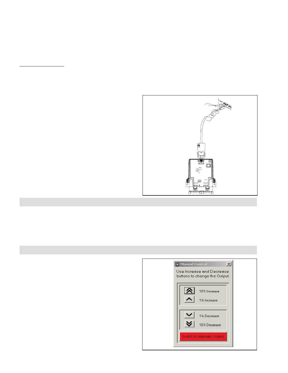
.0 MaNUaL OPeRaTION OF RSD100 OUTPUT
To achieve a stable dancer arm before the RSD100 is
tuned, the RSD100 OUTPUT may have to be controlled
manually. Manual control of the RSD100 OUTPUT can
be achieved by pressing the SWITCH TO MANUAL
CONTROL button on the Diagnostics Screen (Refer to
Figure 18). The increase buttons increase the RSD100
OUTPUT to the brake, clutch or drive. Conversely, the
decrease buttons decrease the RSD100 OUTPUT to
the brake, clutch, or drive. The 10% buttons increase/
decrease the output by 10% steps. The 1% buttons
increase/decrease the output by 1% steps. Manual
operation provides enough output resolution to provide
stability for a quick measurement or reading.
Figure 10