Rail setup panel setup – Woodhaven 5434: Frame and Panel Master User Manual
Page 2
BEFORE BEGINNING
Identify and verify that you have all the parts listed. The
Frame & Panel Master was designed to be used with Woodhaven
Standard Door Templates for the router. It will hold parts between
5" and 20" long/wide and up to 7/8" thick. Read the instructions
carefully at least once before beginning.
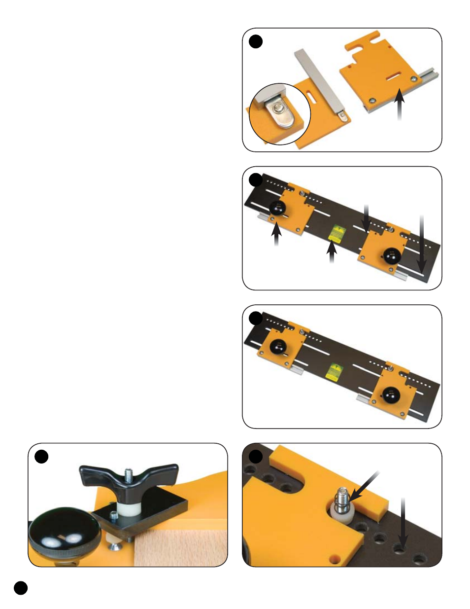
ASSEMBLY
Insert two 5/8" screws (5775B) thru the holes indicated in
each fence and start an oval nut (5760B), flat side first, on the end
of each screw. Slide a 6" one track (4206) on the oval nuts, posi-
tion them on the fences as shown and tighten the screws. See fig. 1.
Attach the fences to the base (5434B), but first determine
whether you'll be cutting panels or rails.
For rail work the fences should be placed with their notched
edges facing each other. See fig. 2.
For panel work the fences should be placed with their straight
edges facing each other. See fig. 3.
Install two 1-1/2'' bolts (HB050), one on each side, thru the
bottom of the base into slot "C". Install a fence on each bolt, fol-
lowed by a 5/8'' long spacer (BUSH004) and a knob (5590). The
6" One track attached to each fence should be snug against the edge
of the base. Slide the fences as far apart from each other as pos-
sible on the base and tighten the knobs.
Select the Standard Door Template you wish to use. You will
not use the fences that came with the Standard Door Template Set
when using the Frame & Panel Master.
Center the template side-to-side on the base and install two
1-1/4" bolts (HB040) through the bottom of the base, into the holes
in slot "A" of the base that match up with the holes in the template.
Tighten the bolt in place with a knob (5521) and place a spring
(Spring3) on each bolt. See fig. 4.
Insert a 3" bolt (HB060) thru the bottom of the base in slot
"B", one on each side, thru the hole in the fence nearest the work.
Screw a knob (5521) on to each 1" screw (MF020) and install
the screw/knob in the threaded hole in each clamp pad (5434C).
Adjust the head of the screw to match the thickness of the wood
you're machining and tighten the knob. See fig. 5
The clamp pad slips onto the bolt, followed by a 3/8" spacer
(BUSH050) and knob (5560) which hold the template/work to the
base. The fences are slotted for optimum placement of the fence
knobs in relation to the clamp pads. See fig. 5
Attach One Track
to fence
1
1
2
3
4
Rail Setup
Panel Setup
5434B
Base
Slot C
Slot B
5434A
Fence
Holes/Slot A
HB040 &
Spring3
Clamp Pad
5521
MF020
5560
BUSH050
HB060
5