Woodhaven 6010: HD Mortise Table User Manual
Page 4
3
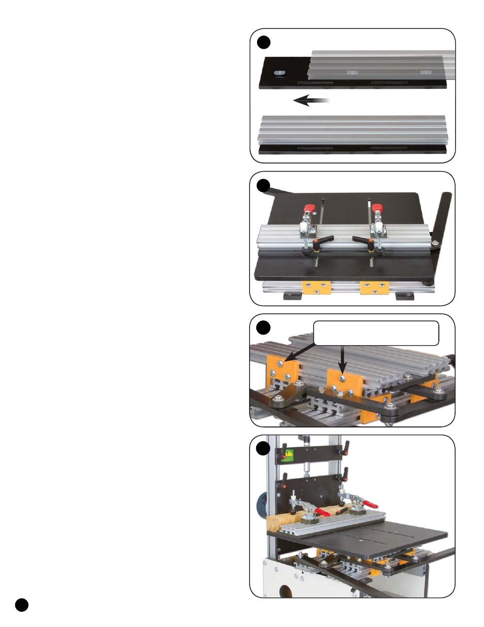
ATTACH FENCE TO TABLE
Insert a 5/8" screw (MF006) thru the three countersunk
holes in the Table Fence (6010C) and start an oval nut
(5760B - flat side first) on the end of each screw. Slide
the center T-slot of the 16" Ultra Track (4416) on to the
oval nuts, center it end-to-end and flush with the edge of
the Table Fence and tighten the screws. See fig. 10.
From the underside of the 15-3/4" Phenolic Table, insert
a 1" bolt (HB030) thru each of the two slots in the table. Using
the slots in the Table Fence, place the Table Fence on the bolts.
Install two washers (WB002) and a ratchet handle (5860) on
each bolt and tighten the fence at the desired angle. See fig. 11.
Follow the directions included with the two
Inboard Toggle Clamps (6305IC) and install them on
the Ultra Track fence where desired. See fig. 11.
ADJUSTMENT
The screw indicated on the glide controls the tension
on the tightener, which controls how hard or easy the HD
Mortise Table moves. There are a total of eight glides/
tighteners. The initial adjustment to the tighteners is made
at our factory and, under normal circumstances, they won’t
need adjustment for a year or more, if ever. See fig. 12.
If you feel the HD Mortise Table moves too hard, too
easy, or has too much play, these screws are how you’ll adjust
the tension on the tighteners. First make sure it’s clean and
there is no debris causing the problem. If you need to adjust the
tighteners, first snug the screws using a #3 Phillips screwdriver.
Do not overtighten or you may strip the tighteners! Next loosen
the screws approximately 1/8th turn and test how well the
Table moves. Tighten or loosen the screws to adjust the tension
on the tighteners according to your preference. See fig. 12.
USING THE MORTISE TABLE
Do not overload the HD Mortise Table. For safety
reasons, we recommend that the work not weigh over
20 lbs. Make sure long parts have additional outboard
support to prevent damage to the HD Mortise Table.
Insert the work against the Table Fence and
tighten the toggle clamps. Set the stops for the
desired left-to right travel (mortise length) and
depth of cut (mortise depth). See fig. 4 & 13.
Make sure the work and Mortise Table are not touching
the bit, then turn on the router. Using the Handles, move the
work/table against the left stop and plunge the work into the
bit, "drilling" a hole. Retract the work, move the work/table
against the right stop and plunge the work into the bit again,
"drilling" a second hole. Retract the work from the bit almost
completely, then feed the Mortise Table from right-to-left and
left-to-right as you gradually feed the work forward into the bit.
For best results, you should not cut deeper then the bit
diameter in each mortising pass. For example, a 1/4" bit should
not cut deeper than 1/4" per pass.
©Copyright WOODHAVEN INC. 11/15/10
(800) 344-6657 or WWW.WOODHAVEN.COM
11
10
13
12
12
Adjust tension on tighteners here
(eight places total) if necessary.