Vortech 2003-2006 G35 User Manual
Page 35
P/N: 4NZ020-010
©2008 Vortech Engineering, LLC
All Rights Reserved, Intl. Copr. Secured
04JUN08 v6.0 Nissan 350Z(4NZv6.0)
17
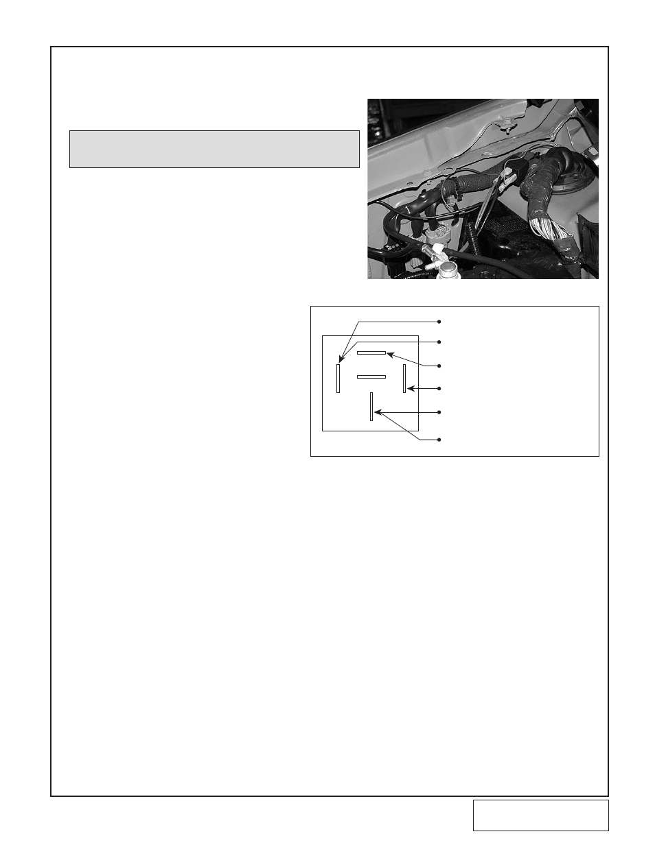
Fig. 11-a
11. 2005 “REV-UP” AND 2006 VEHICLE TIMING CONTROLLER INSTALLATION (For
2003-2005 Standard Engine Vehicles, Skip This Section and Proceed with Section 12)
A.
Install the supplied “piggyback ECU” per the instruc-
tions supplied with the unit.
b.
Install the supplied fuel pump relay in the passen-
ger’s side/rear of the engine compartment as shown.
(See Fig. 11-a.)
C.
Run the white-with-red-stripe wire and the brown
wire from the “piggyback ECU” connector to the
relay.
D.
Attach the white-with-red-stripe wire to terminal #85
on the relay using the supplied slide connector.
(See Fig. 11-b.)
E.
Attach the brown wire and the supplied black wire to
terminal #30 on the relay.
F.
Attach one end of the supplied fuse hold-
er pigtail and the supplied red (fuel pump
power) wire to terminal #86 using a
female slide connector.
G.
Attach one end of the supplied black (fuel
pump ground) wire to terminal #87.
H.
Attach the open end of the fuse holder to
the positive battery terminal using the
supplied ring terminal connector.
I.
Attach the fuel pump power wires to their
respective terminals using the supplied
ring terminal connectors.
J.
Install the fuel pump fuse in the fuse holder
and install the supplied plastic wire loom over the
wires.
NOTE: There is no “accessory cable functionality” used with
the supercharger kit and it should be removed from
the ECU if equipped.
#86 FEMALE SLIDE: FUSE HOLDER
(WITH PIGTAILS) TO BATTERY (+)
#87 - 7' BLACK 14GA WIRE
w/BARE END (TO FUEL PUMP (-))
#85 - 4' WHITE/RED FROM
UNICHIP CONNECTOR
#30 - 4' BROWN WIRES (2) FROM
UNICHIP CONNECTOR
7' RED 14GA w/BARE END
(TO FUEL PUMP (+))
1' BLACK 14GA WIRE w/3/8" RING
TERMINAL CONNECTOR (TO
CHASSIS GROUND)
Fig. 11-b