Timing controller installation, cont’d – Vortech 2003-2006 G35 User Manual
Page 33
P/N: 4NZ020-010
©2008 Vortech Engineering, LLC
All Rights Reserved, Intl. Copr. Secured
04JUN08 v6.0 Nissan 350Z(4NZv6.0)
15
10. TIMING CONTROLLER INSTALLATION, cont’d
J.
Connect the
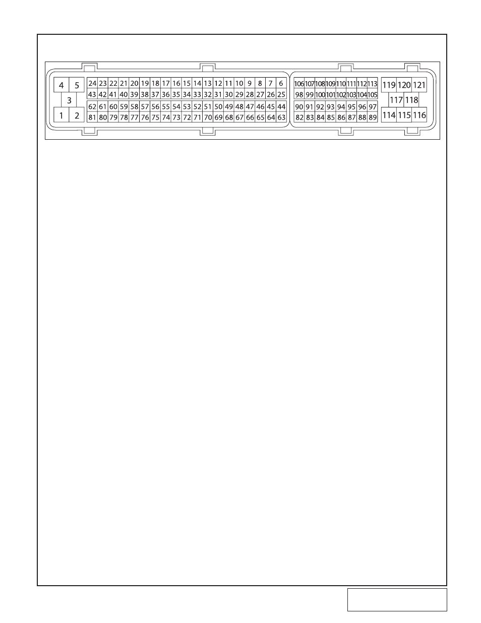
GREEN wire to the wire leading to the MAF sensor. (Terminal 51).
K.
Connect the
VIOLET wire to the wire leading to the ECU MAF sensor input.
L.
Locate the crank sensor signal wire and cut it (Terminal 13).
M.
Connect the
bLUE wire to the wire leading to the crank sensor.
N.
Connect the
bLUE/WHITE wire to the wire leading to the ECU crank sensor input.
O.
Locate and cut the
CAM 1 sensor signal wire and cut it. (Terminal 33).
P.
Connect the
YELLOW wire to the wire leading to the cam sensor.
Q.
Connect the
YELLOW/bLACK wire to the wire leading to the ECU cam sensor input.
R.
Locate and cut the
CAM 2 sensor signal wire and cut it (Terminal 14.)
S.
Connect the
TAN wire to the wire leading to the cam sensor.
T.
Connect the
TAN/bLACK wire to the leading to the ECU cam sensor input.
U.
Connect the large 12-gauge
RED wire to the battery (+) positive terminal, using the sup-
plied ring terminal connector.
V.
Reinstall the ECU plug and interior panels.
W.
The
STRIPED RED wire needs to be connected to the Positive terminal of the previous-
ly installed fuel pump. Use the supplied plastic wire loom to enclose the wire. Route it
down the passenger’s side of the engine and secure it away from heat and sharp
edges.
X.
The vacuum hose on the timing controller should be connected to intake manifold vacu-
um using the supplied TEE and hose.
Y.
Reinstall the battery covers.
Skip to Section 12
Fig. 10-c / As viewed from the back of the connector (Where the wires are inserted)