Vortech 2003-2006 G35 User Manual
Page 29
P/N: 4NZ020-010
©2008 Vortech Engineering, LLC
All Rights Reserved, Intl. Copr. Secured
04JUN08 v6.0 Nissan 350Z(4NZv6.0)
11
Fig. 7.2-b
Fig. 7.2-d
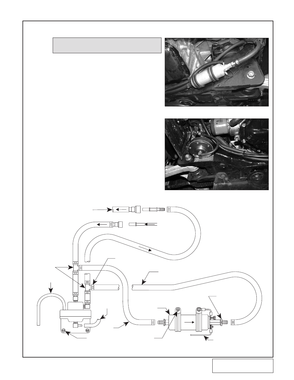
E.
Cut the FMU line that goes to the vehicle’s FUEL
TANK and install a 5/16" TEE fitting with clamps.
Connect the TEE to the INLET of the supplied fuel
pump. (See Fig. 7.2-c.)
F.
Cut the FMU line that goes to the vehicle’s ENGINE
and install a 5/16" TEE fitting with clamps. Connect
the TEE to the OUTLET of the supplied fuel pump.
G.
Remove the vacuum cap from the small bump tube
on the front passenger’s side on the intake manifold.
Use the supplied vacuum hose to connect the pump
tube to the fitting on the FMU cover. (See Fig.
7.2-d.)
H.
Install a short length of vacuum hose onto the pro-
truding roll-pin that is installed into the FMU body.
Use a small amount of sealant and route and secure
the hose so that the open end is pointed towards the
ground to minimize water entrance. (See Fig. 7.2-c.)
NOTE: The positive (+) fuel pump wire will be
connected in Section 10.
7.2 FUEL MANAGEMENT UNIT (FMU) AND FUEL PUMP INSTALLATION, cont’d
MARK AND DRILL HOLES INSTALL
THE SUPPLIED SHEET METAL SCREWS TO HOLD
THE FUEL MANAGEMENT UNIT AND FUEL PUMP
CUT SUPPLIED FUEL HOSE
TO LENGTH (~39")
FACTORY SUPPLY
LINE FROM FUEL
TANK
5/16" HOSE
BARB TEES
5/32" VENT
HOSE (~8")
~18"
(VERIFY THAT
COPPER WASHERS
ARE INSTALLED AND
FITTINGS ARE TIGHT)
RED WIRE WITH STRIPE (FROM
IGNITION TIMING CONTROL BOX)
FACTORY FLEXIBLE LINE
TO INTAKE MANIFOLD
SUPPLIED
FUEL PUMP
INSTALL AND
TIGHTEN CLAMPS
USING STEPLESS
CLAMP PLIERS
5/32" HOSE
(CONNECTED
TO MANIFOLD
PRESSURE)
Fig. 7.2-c