Vortech 2003-2006 G35 User Manual
Page 26
P/N: 4NZ020-010
©2008 Vortech Engineering, LLC
All Rights Reserved, Intl. Copr. Secured
04JUN08 v6.0 Nissan 350Z(4NZv6.0)
8
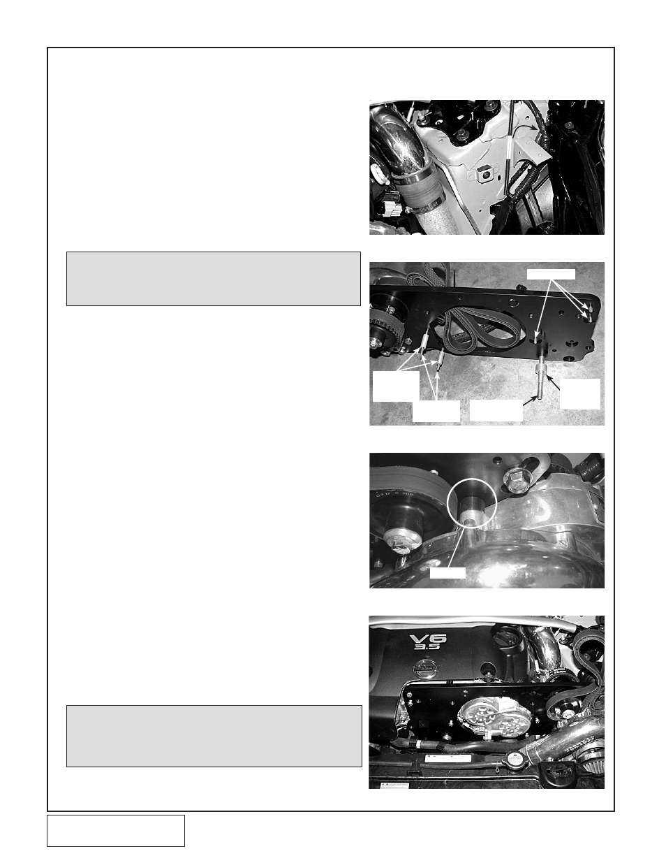
6. SUPERCHARGER MOUNTING PLATE INSTALLATION (2005 and Later
“Rev-Up” Engines)
NOTE: Oil in the supercharger is gravity drained to the oil
pan. Trim the supplied oil drain hose as necessary
so that it is continuously sloping down towards the
oil pan. Avoid dips, kinks, etc.
A.
Remove the wire loom push pins and re-route the
wires around the outside (driver’s side) of the sheet
metal bracket. (See Fig. 6-a.)
b.
(Non oil fed applications skip this step) Install the
supplied Ø1/2" fabric-braid oil drain line onto the
supercharger fitting and tighten the supplied hose
clamp.
C.
(Non oil fed applications skip this step) Install the
supplied 1/8"NPT x -4 straight fitting into the super-
charger oil feed nozzle using motor oil on the
threads. Attach the supplied oil feed hose to the fit-
ting and tighten.
NOTE: Use clean oil on the pipe (tapered) threads. Teflon
tape or sealant is not recommended as it may loos-
en and cause blockage of the small oil feed orifice
resulting in supercharger failure.
Fig. 6-b
Fig. 6-a
Fig. 6-c
Fig. 6-d
D.
Install the mounting plate to engine screws through
through the mounting plate in the position shown.
(See Fig. 6-b.) These screws must be installed first
because once the supercharger is mounted, some of
them can not be installed.
E.
Install the supplied 6-rib belt around the 6-rib alumi-
num pulley on the mounting bracket assembly. Install
the supercharger onto the mounting plate with the
supplied .53" spacers (see Fig. 6-c) between the
supercharger and the mounting plate. Secure with
the four 3/8" x 1-3/4" bolts.
F.
Install the supplied gilmer (toothed) belt around the
pulleys on the mounting plate assembly.
G.
Install the three various mounting plate spacers onto
their respective screws. (See Fig.
6-b.) A small dab of sealant between the spacer and
the mounting plate may help retain them during
installation.
H.
Position the supercharger mounting plate assembly
in front of the engine and start all of the mounting
screws. (See Fig. 6-d.)
I.
Make sure that the coolant hose is routed in front of
the supercharger mounting plate.
J.
(Non oil fed applications skip this step) Verify that
the oil drain hose is routed as smoothly as possible
and connect it to the fitting on the oil pan. Tighten a
hose clamp on this connection. Secure the oil drain
hose and the A/C line away from the A/C pulley with
zip-ties. Trim the drain hose length if
necessary.
M6 x 20mm
M12 x 110mm
M6 x 70mm
Ø.5" x 1.175"
SPACERS
Ø1" x .602"
SPACER
SPACER