Vortech 2003-2006 G35 User Manual
Page 32
P/N: 4NZ020-010
©2008 Vortech Engineering, LLC
All Rights Reserved, Intl. Copr. Secured
04JUN08 v6.0 Nissan 350Z(4NZv6.0)
14
A.
Remove the inspection cover over the battery.
Remove the plastic clips securing the larger cover
over the battery and remove it as well.
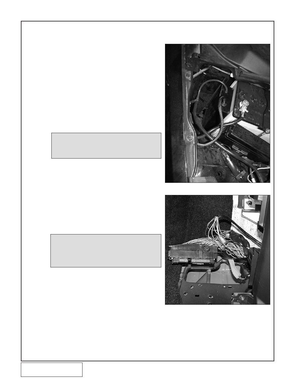
b.
Using the supplied adhesive backed Velcro, position
the ignition timing control computer next to the bat-
tery as shown. (See Fig. 10-a.)
C.
Run the wires through the firewall grommet next to
the main ECU wiring harness.
D.
The ECU is located behind the passenger’s side kick
panel. Remove the door scuff panel and the kick
panel.
E.
Remove the ECU harness connector by pulling on
the lever. Remove the plastic cover from the connec-
tor so that the wires can be traced to their respective
terminals. (See Fig. 10-b.)
10. 2003-2005 STANDARD ENGINE TIMING CONTROLLER INSTALLATION (For 2005
“Rev-Up”
and 2006 Vehicles Skip to Section 11)
Fig. 10-a
NOTE: Always verify each pin location. Wire
color is provided as a reference only. If
there is a discrepancy between wire
color and pin location, disregard wire
color and use the numbered pin location.
Fig. 10-b
F.
See Fig. 10-c for the ECU harness connector termi-
nal layout as viewed from the side of the connector
where the wires are inserted.
G.
Connect the thin 20Ga
RED wire to battery positive
switched by the ignition (ECU harness connector ter-
minal 109). Use the supplied T-Tap and spade con-
nector.
H.
Connect the
bLACK wire to the ECU ground
(Terminal 115). Use the supplied T-Tap and spade
connector.
I.
Locateand cut the MAF sensor signal wire (Terminal
51).
NOTE: Soldered wire connections are more
sound than crimp-on connectors because
they can be inspected. It is up to the
installer to guarantee good connections.
If there is any doubt, or the vehicle per-
forms erratically, solder and insulate each
connection.