Vortech 2003-2006 G35 User Manual
Page 28
P/N: 4NZ020-010
©2008 Vortech Engineering, LLC
All Rights Reserved, Intl. Copr. Secured
04JUN08 v6.0 Nissan 350Z(4NZv6.0)
10
7.1 FUEL MANAGEMENT UNIT (FMU) RECALIbRATION (2005 G35 Only)
NOTE: This step applies to Model Year 2005 Infiniti G35 vehicles only! For all
others, skip the following and proceed with Section 7.2.
A.
Remove the six allen-head screws on top of the fuel
management unit (FMU).
b.
Remove the diaphragm and 7:1 disk and ring from
inside of the FMU.
WARNING:
Do not remove the four screws hold-
ing the valve body. Once taken apart,
the valve would have to be replaced.
C.
Install the replacement 6:1 ring (with the notched
part facing FMU body) around the four screws inside
the FMU. (The 6:1 components are smaller diameter
than the 7:1).
D.
Place the 6:1 disk inside the ring next to the piston.
E.
Install the new diaphragm and carefully line up the
holes to the body.
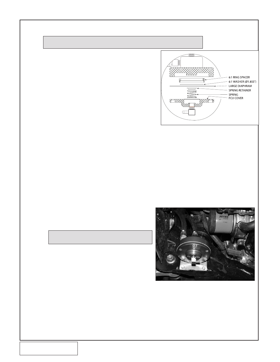
F.
Place the spring retainer in the center of the dia-
phragm with the spring between it and the cover.
(See Fig. 7.1-a.)
G.
Reinstall the FMU cover with the six allen-head
screws. Do not over-tighten the screws. The correct
torque is 24 in/lb (2ft/lb).
7.2 FUEL MANAGEMENT UNIT (FMU) AND FUEL PUMP INSTALLATION
Fig. 7.2-a
NOTE: Ensure that the fuel lines are not kinked
and have smooth bends, no chafing etc.
A.
Install the FMU in the location shown in
Fig. 7.2-a using the supplied sheet metal screws
(drill a pilot hole at each location before installing the
screw.)
b.
Disconnect the fuel line fitting on the passenger’s
side frame rail near the engine.
C.
Connect the FMU hoses to the respective fittings on
the fuel lines. (See Fig. 7.2-c.)
D.
Install the fuel pump on the driver’s side of the front
cross member as shown. (See Fig. 7.2-b.) Run a
ground wire from the negative terminal on the fuel
pump to one of the mounting screws.
Fig. 7.1-a