Throttle body ducting installation – Vortech 2003-2006 G35 User Manual
Page 22
P/N: 4NZ020-010
©2008 Vortech Engineering, LLC
All Rights Reserved, Intl. Copr. Secured
04JUN08 v6.0 Nissan 350Z(4NZv6.0)
4
A.
Use the supplied hose union to attach the supplied
5/8" hose to the engine breather hose that was dis-
connected from the factory air-inlet duct.
b.
Attach the MAF to the supplied duct using the sup-
plied 6mm hardware. The bend in the duct should
point the same way as the plug on the MAF. Ensure
the MAF O-ring is present.
C.
Using the supplied 3" tube and sleeves, attach the
MAF to the throttle body. Plug in the MAF electrical
connector.
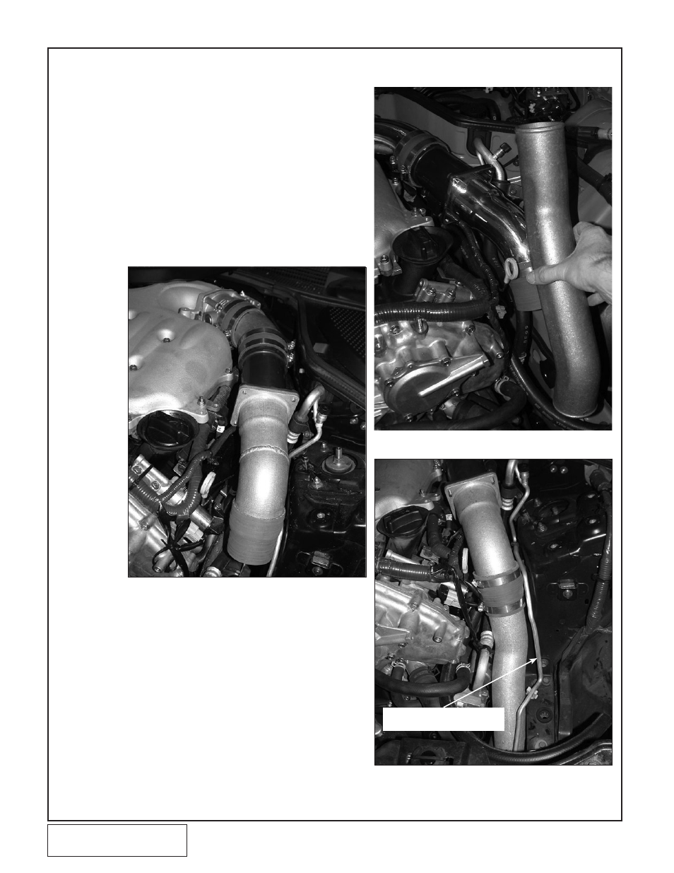
D.
Install a 2.75" to 2.5" reducer onto the end of the
duct. (See Fig. 4-a.)
E.
Install the cast intermediate duct into the vehicle
(see Fig. 4-b) and then slide it up into the reducer
sleeve. The duct should be routed between the flexi-
ble A/C line and the frame with the bent end pointed
down. (See Fig.
4-c.)
F.
Install and tighten clamps on each connection.
(These may need to be loosened after the super-
charger is installed to improve the fit.)
4. THROTTLE bODY DUCTING INSTALLATION
Fig. 4-a
Fig. 4-b
Fig. 4-c / (350Z)
BEND A/C LINE TO PROVIDE
DUCT CLEARANCE AS NEEDED