Charge cooler installation – Vortech 2003-2006 G35 User Manual
Page 30
P/N: 4NZ020-010
©2008 Vortech Engineering, LLC
All Rights Reserved, Intl. Copr. Secured
04JUN08 v6.0 Nissan 350Z(4NZv6.0)
12
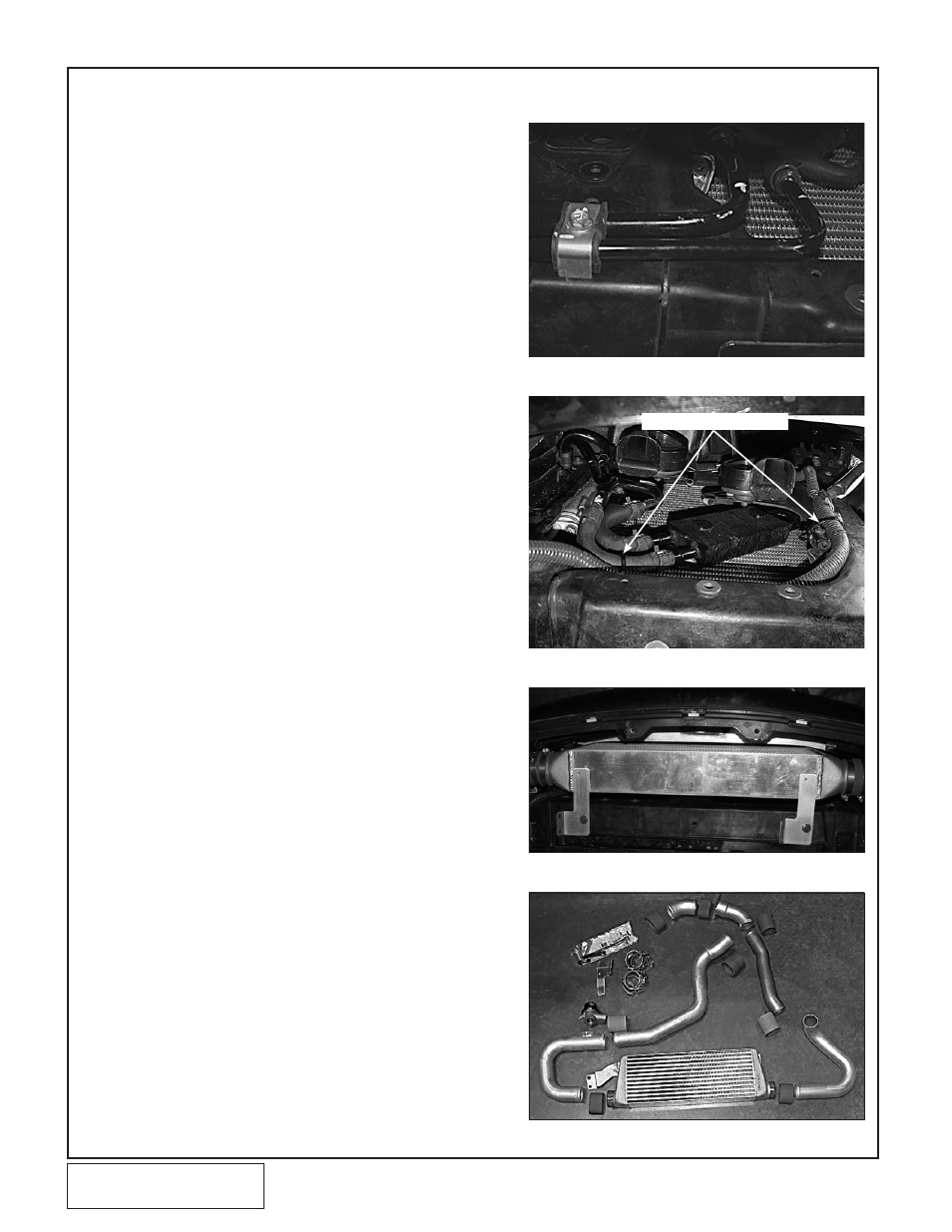
A.
Remove the wire loom hold-downs from the front of
the radiator core support. Remove the brackets
securing the power steering cooler lines to the core
support.
• G35 Vehicles, All: Remove the foam inner bum-
pers on the driver and passenger sides of the
Charge Air Cooler mounting location. Locate and
remove the power steering hard line brackets.
Cut the threaded section off of the bracket just
removed. Install the threaded piece behind the
core support and clamp the hard lines to the front
of the core support as shown in
Fig. 8-a.
• G35 Vehicles, Automatic Only: Remove the
two rubber lines from the transmission cooler.
Remove the two rubber transmission cooler lines
from the junction on the passenger’s side frame
rail. Remove the hard lines with the rubber lines
still attached from the vehicle. Once the transmis-
sion cooler has been repositioned, connect the
cooler to the junction using the rubber line provid-
ed. Secure with factory clamps.
b.
Using the supplied adhesive backed foam to insulate
the power steering cooler from the radiator, position
it as shown in Fig. 8-b. Install the snap connectors
on the free end. Cut off any excess that would inter-
fere with radiator fan operation.
C.
Rotate any clamps that are pointing toward the front
of the vehicle so that they will not contact the charge
air cooler. Use the supplied zip-ties to secure the
wire loom to the air temp sensor and the power
steering hose.
D.
Temporarily attach the two supplied matching metal
brackets to the bottom of the radiator core support
using two of the factory splash pan screws. (See
Fig. 8-c.)
E.
Attach the remaining metal bracket to the charge
cooler using the supplied 1/4" x 3/4" hardware. (See
Fig. 8-d.)
F.
Install the cooler in front of the radiator and rotate
the metal brackets to support it as shown.
G.
Mark the plastic panels on either side of the cooler
for passage of the Ø2-1/2" cooler tubes. Remove the
cooler and drill a horizontal 2.5" hole (minimum)
through each of the plastic panels. (If the vehicle has
foam blocks that interfere with the discharge ducts,
remove the foam from the vehicle.)
H.
Reinstall the cooler. Connect the upper cooler brack-
et to two of the factory screws that secure the front
bumper. Align cooler for best fit and tighten the four
screws that attach the bracket.
8. CHARGE COOLER INSTALLATION
Fig. 8-b
Fig. 8-a
SECURE WIRE LOOM HERE
Fig. 8-d
Fig. 8-c