Vortech 1997-2001 5.2L/5.9L Durango/Dakota User Manual
Page 17
P/N: 4CE020-010
© 2000 Vortech Engineering, Inc.
All Rights Reserved, Intl. Copr. Secured
18AUG00 V 2.1
(Dodge 5.9L Durango/Dak-2)
7
9A. IGNITION/BOOST CONTROL INSTALLATION (1997-99 Dakota/Durango only)
A. Remove the four phillips head screws attaching
the plastic tray (located beneath the tilt-up con-
sole cover) to the armrest/console located be-
tween the two front seats. Remove the six con-
sole mounting screws with an 8mm socket and
lift the center console out of the vehicle (four
screws are located underneath the two cup
holder mats in the armrest/console). From the
bottom side of the console, remove the six
phillips head screws attaching the plastic front
cover to the console.
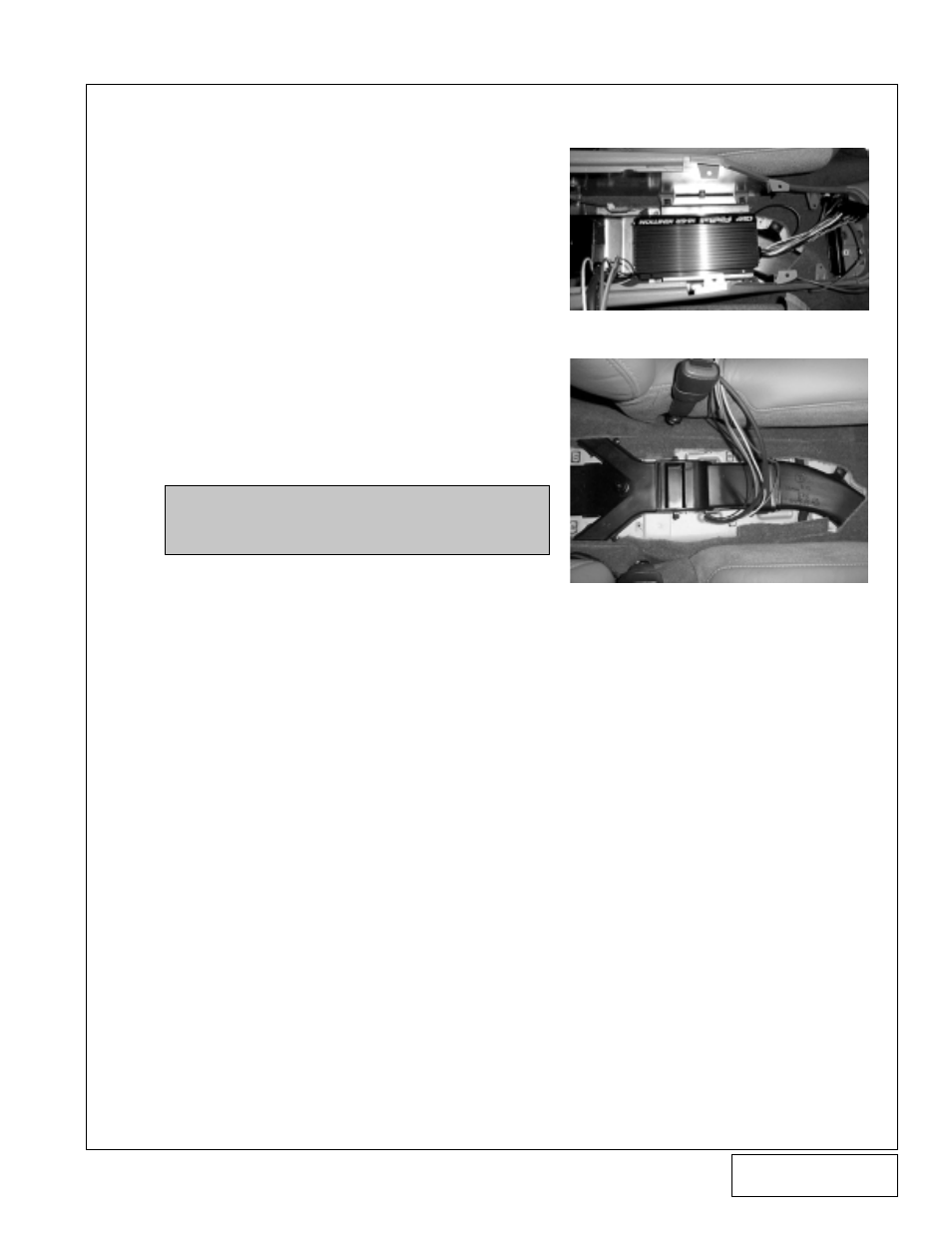
B. Position the main ignition module onto the metal
tray, (offset unit to keep mounting screws from
puncturing air duct). (See
Figure 9A-a
.) Mark
and drill holes using a #25 drill bit. Secure
ignition module with the provided #12 hardware
to the metal tray.
C. With the center console removed, mark and drill
a 5/8" hole into the floor. (See
Figure 9A-b
.)
D. Under the hood, cut both wires at the coil con-
nector, leaving a few inches of wire on the
connector to work with. Attach the 10' red 18 GA
wire extension using the supplied connectors to
the green wire coming from the factory harness
to the coil. Attach the 10' white 18 GA wire
extension to the black wire coming from the
factory harness coil. Refer to the ignition wiring
diagram.
E. Attach the supplied 10' orange 18 GA wire
extension to the green wire on the factory coil
connector plug and the 10' black 18 GA wire
extension to the black wire on the same plug.
F.
Attach a 12 GA eyelet terminal to one end of the
supplied fuse holder and a solderless connector
to the opposite end. Connect the 10' red 12 GA
wire to the solderless connector. Install the wired
12 GA eyelet assembly onto the positive acces-
sory terminal, located on the fuse box underhood.
G. Attach the supplied 5/32" vacuum line to the
capped port on the side of the intake manifold.
Route the vacuum line from the right side of the
engine along the firewall. Route all five wires and
vacuum line down the driver's side of the vehicle
along the frame (securing along the way with tie
wraps) to the previously drilled hole in the floor.
AVOID EXHAUST PIPES AND SHARP OB-
JECTS! Pull wires and vacuum line into passen-
ger compartment. (See
Figure 9A-b
.)
NOTE: Ensure there is room for wires (that
are to be routed into console) under-
neath vehicle and inside console.
Figure: 9A-a
Figure: 9A-b