Vortech 2011-2012 6.4L Hemi Challenger User Manual
Page 23
P/N: 4CL020-020 v1.0, 12/02/2014
©2014 Vortech Engineering, Inc
All Rights Reserved, Intl. Copr. Secured
13
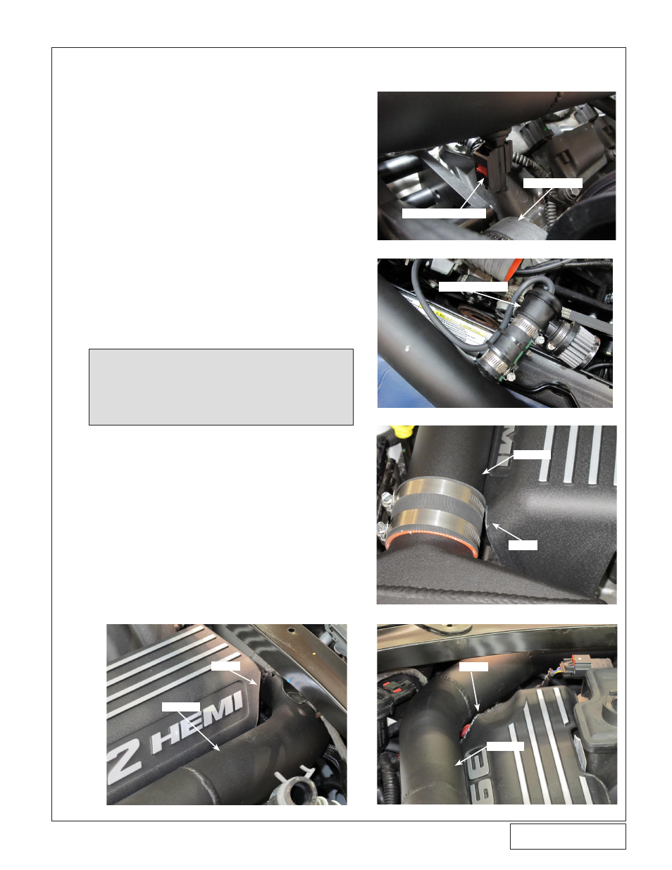
8. CHaRGE aIR COOLER/DISCHaRGE aSSEMbLY INSTaLLaTION, CONT’D
NOTE: To keep the vacuum hose from rubbing
against the accessory drive belt, we suggest
using zip ties to hold the vacuum hose against
the 1” bypass valve hose. (See Fig. 8-k)
R. Verify that all of the discharge tubes are in place
& proceed to tighten all of the hose clamps. Make
any necessary adjustments to the tubes or sup-
port brackets for proper fitment. The hose clamps
on the silicone coupler joining discharge tube B
& discharge tube C must be tightened using an
8mm socket, swivel joint & a long extension. The
hose clamps must be pushed towards the firewall
to make clearance for the windshield wiper arms.
Failure to do so will result in the windshield wiper
arms coming into contact with the hose clamps.
S. Locate the engine covers & modify them so they
clear discharge tubes “B” & “C”.
(See Figs. 8-l, 8-m, 8-n)
O. Reconnect the IAT Sensor plug to the IAT sensor,
making sure the wire is clear of the cog belt. (See
Fig. 8-j)
P. Locate discharge tube A. Install the supplied
bypass valve & filter onto the welded barb using
the supplied 1” hose. Connect the supplied 5/32”
vacuum hose to the bypass valve & route under
the throttle body, across the driver’s side of the
engine, connecting the other end of the vacuum
hose to the previously installed vacuum tee on
the brake booster line. Use zip ties to secure the
vacuum hose to the fuel injector harness.
Q. Place discharge tube A in between the charge air
cooler & supercharger outlet using the supplied
silicone couplers & hose clamps. The end of the
tube with the bends will go towards the super-
charger outlet. Be sure that the bypass valve is
pointing straight down towards the bottom of the
vehicle, making sure that the bypass valve & filter
are clear of the accessory drive pulleys & belt.
Fig. 8-j
Fig. 8-k
Fig. 8-l (Passenger Side)
Fig. 8-m (Passenger Side)
Fig. 8-n (Drivers Side)
TRIM
TRIM
TRIM
IAT SENSOR PLUG
COG BELT
BYPASS VALVE
TUBE B
TUBE B
TUBE C