Spectrum Controls 140 AUI 040 00sc User Manual
Page 27
Quantum Series 140 AUI 040 00sc
28
4.3
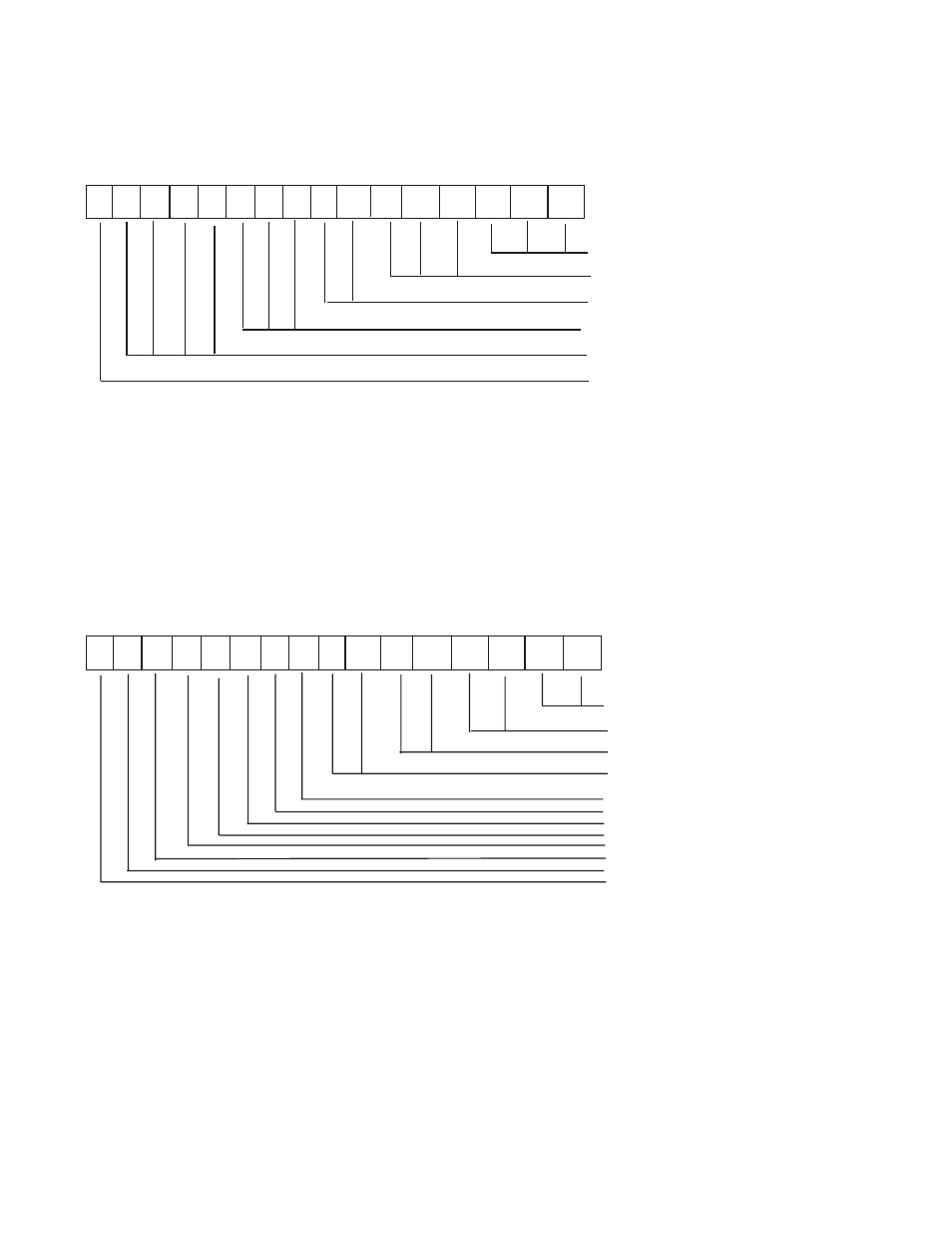
Channel Status (Registers 3x+ 0 through 3x+7)
(Registers 3x+ 0 through 3x+7) Status Mode 1:
1 2 3 4 5 6 7 8 9 1 0 111 2 1 3 1 4 1 5 1 6
Input Type Echo
Voltage Range Echo
Current Range Echo
Thermocouple Range Echo
RTD Type Echo
RTD Wire Number Echo
3x+0 . . . 7 RTD Wire Number Echo: Bit 1
3x+0 . . . 7 RTD Type Echo: Bits 2-5
3x+0 . . . 7 Thermocouple Range Echo: Bits 6-8
3x+0 . . . 7 Current Range Echo: Bits 9-10
3x+0 . . . 7 Voltage Range Echo: Bits 11-13
3x+0 . . . 7 Input Type Echo: Bits 14-16
(Registers 3x+ 0 through 3x+7) Status Mode 2:
1 2 3 4 5 6 7 8 9 1 0 111 2 1 3 1 4 1 5 1 6
Resistance Range Echo
Filter Echo
Format Echo
Fault Detect Echo
Temperature Units Echo
Calibration Error
Configuration Error
Over Range
Under Range
Broken Input
CJC Error
Bank Number
3x+0 . . . 7 Bank Number: Bit 1
3x+0 . . . 7 CJC Error Echo: Bit 2
3x+0 . . . 7 Broken Input Echo: Bit 3
3x+0 . . . 7 Under Range Flag: Bit 4
This is a nonfatal under range flag. The bit is set to “1” when an input value is read within one count of the
minimum range value. When the input value is within normal limits the flag is automatically reset to “0.”