4 zoom screen configuration – Spectrum Controls 140 AUI 040 00sc User Manual
Page 11
Quantum Series 140 AUI 040 00sc
12
2.3
General information on data register usage and terminology:
A total of nine 3x level and one 4x level registers are used by the 140 AUI 040 00sc. After you have com-
pleted the runtime file installation, you can go to the I/O Map screen and choose the 140 AUI 040 00sc by
selecting the desired slot, pressing
that slot. For module specific help, press
and 4x level registers to be used. This will then automatically capture nine consecutive 3x level and one 4x
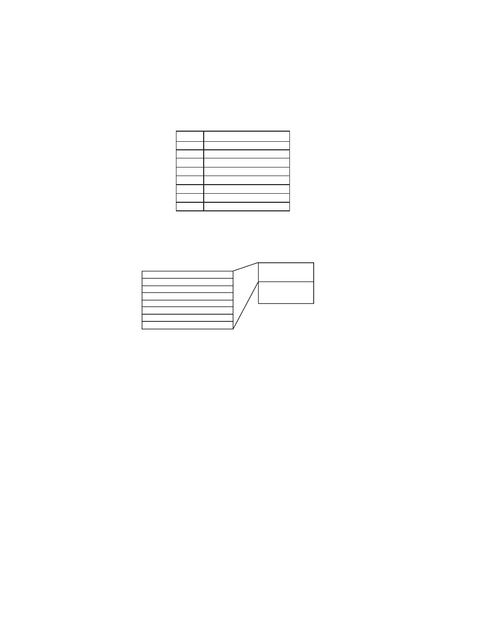
level register for use by the module. The architecture for this 16-channel module is as follows:
4x
Configuration Word
3x + 0 Input Data Channel 1/9
3x + 1 Input Data Channel 2/10
3x + 2 Input Data Channel 3/11
3x + 3 Input Data Channel 4/12
3x + 4 Input Data Channel 5/13
3x + 5 Input Data Channel 6/14
3x + 6 Input Data Channel 7/15
3x + 7 Input Data Channel 8/16
The AUI 040 00sc multiplexes 16 channels of data into eight groups of two channels. Each group can be
selected through the 4x Configuration Word or can automatically sequence through all four groups of channels.
Group 1 Chn 1-4
3x + 0 Input Data Channel 1/9
Group 2 Chn 5-8
3x + 1 Input Data Channel 2/10
3x + 2 Input Data Channel 3/11
Group 3 Chn 9-12
3x + 3 Input Data Channel 4/12
Group 4 Chn 13-16
3x + 4 Input Data Channel 5/13
3x + 5 Input Data Channel 6/14
3x + 6 Input Data Channel 7/15
3x + 7 Input Data Channel 8/16
2.4
Zoom Screen Configuration
For Zoom Screen operation, please refer to Modicon’s Modsoft Programmer User Manual.
! Note: To enter zoom screens from the I/O map menu, highlight the module entry and press the keys
Most of the module setup will be done through the Modsoft zoom screens. The zoom screen setup establishes
the following parameters:
• Input Type
• Input Range
• Filter Frequency Selection
• Input Data Format
• Operational Mode