Spectrum Controls 1734sc-IF4U User Manual
Page 39
Chapter 3: Configuring the 1734sc-IF4U for RSLogix 5000
3-17
User’s Manual Pub. 0300266-01 Rev. A
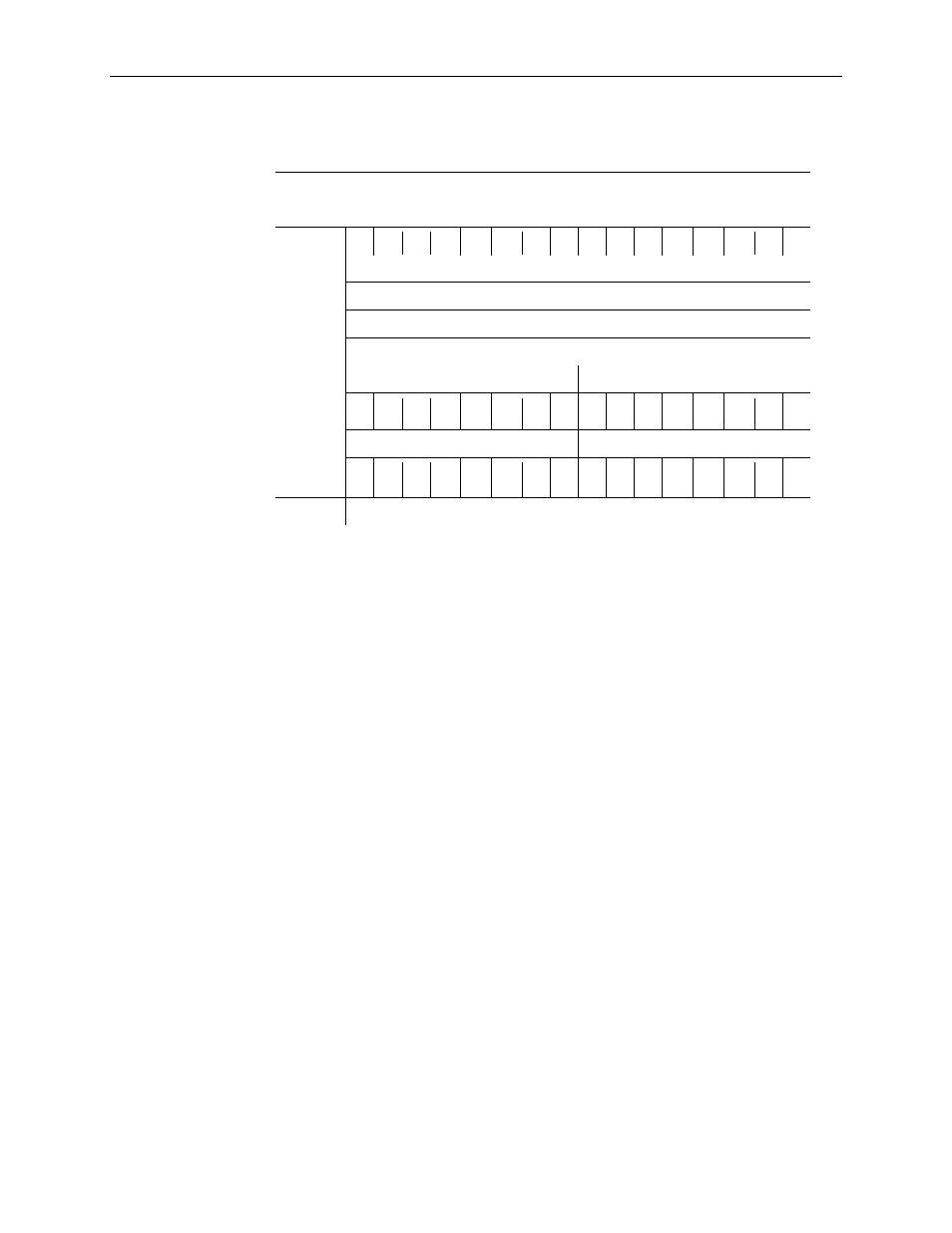
Table 3-4 (IF4U Input Assembly)
Instance:
Description:
Total Size:
100
Analog Only
16 Bytes RSL5K (Dnet 12 bytes)
Bit
15 14 13 12
11
10 09 08 07 06 05 04 03 02 01 00
Analog
data
12 bytes
0x00-
0x0B
Channel 0 Data - INT
Channel 1 Data - INT
Channel 2 Data - INT
Channel 3 Data - INT
Status Byte for Channel 1
Status Byte for Channel 0
n/a n/a n/a OC OR UR n/a CF n/a n/a n/a OC OR UR n/a CF
Status Byte for Channel 3
Status Byte for Channel 2
n/a n/a n/a OC OR UR n/a CF n/a n/a n/a OC OR UR n/a CF
3.6.1 Input Assembly Status Bit Definitions
Under Range and Over Range trip points are determined by the Low Range and High
Range values in the Table 3-3 (Data Formats).
The CF bit is set when any of the other status bits are set.
CF = Channel Fault status; 0 = no error, 1 = fault
UR = Underrange; 0 = no error, 1 = fault
OR = Overrange; 0 = no error, 1 = fault
OC = Open Circuit: 0 = no error, 1 = fault (not valid for all ranges)
n/a = Always 0.