Spectrum Controls 1734sc-IF4U User Manual
Page 21
Chapter 2: Installation and Wiring
2-9
User’s Manual Pub. 0300266-01 Rev. A
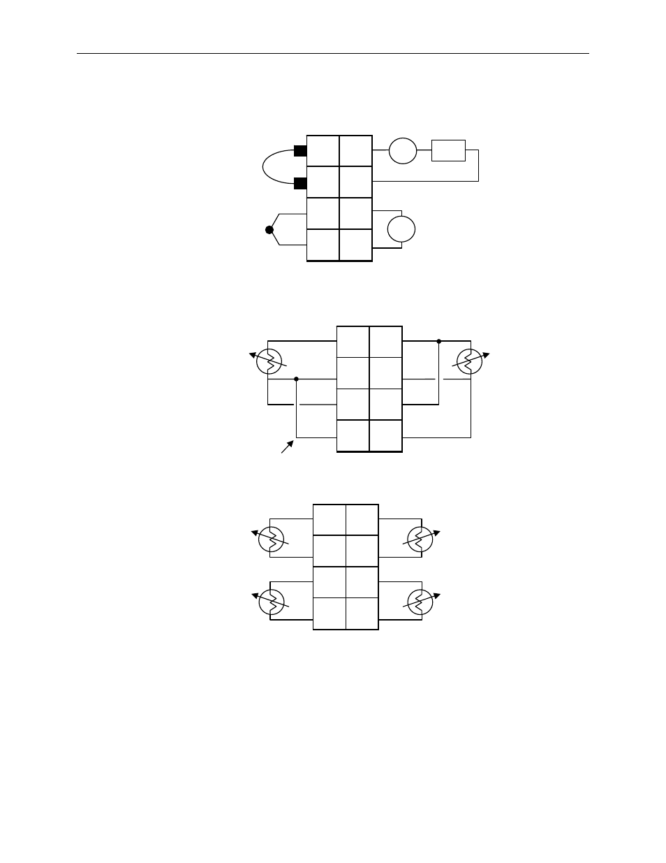
Note: The CJC sensor shown in the diagram above can only be installed
across terminals 0 and 2.
Note: The IF4U supports several input types and can be configured for one
of the following input combinations:
4-channels Voltage + mV + Current
3-Channels Thermocouple
2-Channels 3/4-Wire RTD
4-Channels 2-Wire RTD/Resistance
Or a combination of two or more input types listed above (Ex., 1
Channel of Thermocouple and 1 Channel of 3/4-wire RTD)
0
Ch 0+
2
Ch 0-
4
Ch 1+
6
Ch 1-
1
Ch 2+
3
Ch 2-
5
Ch 3+
7
Ch 3-
2-wire RTD
or
Resistance
2-wire RTD
or
Resistance
2-wire RTD
or
Resistance
2-wire RTD
or
Resistance
0
Ch 0+
2
Ch 0-
4
Ch 1+
6
Ch 1-
1
Ch 2+
3
Ch 2-
5
Ch 3+
7
Ch 3-
3-wire RTD
External
Jumper
4-wire RTD
Figure 4 (Three, and Four Wire RTD)
0
Ch 0+
2
Ch 0-
4
Ch 1+
6
Ch 1-
1
Ch 2+
3
Ch 2-
5
Ch 3+
7
Ch 3-
CJC Sensor
- +
+ -
+
-
24V PWR
Supply
2-wire
XMTR
Thermocouple
Input
4 to 20 mA
Input
Voltage
Input
Figure 3 (Voltage, Current and Thermocouple)
Figure 5 (2-Wire RTD and Resistance)