Setup and operation, Turn on power at its source – SOR Thermal Differential Flow Switch User Manual
Page 5
Form 1024 (08.13) ©SOR Inc.
5/12
Remove the instrument head cover. Turn counterclockwise to expose the electronics.
Turn on power at its source.
Observe that either the red or green LED illuminates.
If neither lamp illuminates, refer to the troubleshootIng section.
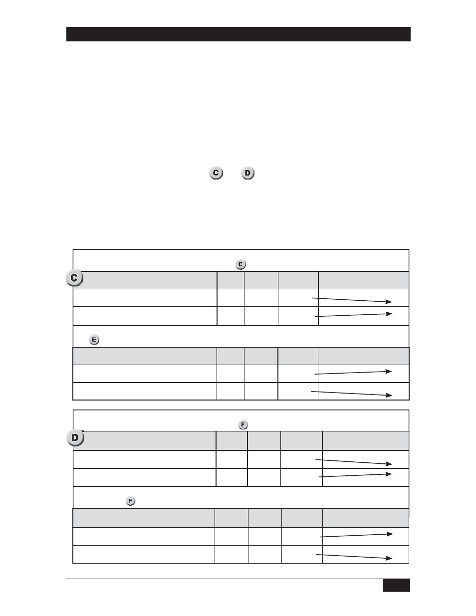
L.E.D. and Relay Status Logic (Fail-Safe)
The L.E.D.s (L1-Red and L2-Green) are an indication of the sensor status (dry or wet) and
are not affected by the position of the fail-safe jumper J-2. The fail-safe jumper J-2 changes
the relay activation status allowing the user to select the fail-safe, power-off condition most
appropriate to the application. Refer to
and
, showing the logic conditions between the
sensors, L.E.D. lights, relay coil and contacts for each position of the fail-safe jumper J-2.
Pre-Operational Check
If the switch is installed and product level is below sensor level, or there is no flow, use
the following procedure to verify preliminary operation.
Setup and Operation
Normal Operation (as set at the factory) The switch comes configured from the factory with the
following operation with the J-2 jumper in the B position. (See
g
g
g
, page 7)
Alternate Operation (Field Selectable) The relay logic may be reversed by moving the J-2 jumper to position A.
(See
, page 7)
Level Sensor Status
L1
Red LED
L2
Green LED
Relay Coil
Status
Relay Contact Status
Dry or Lower Therm. Differential Fluid
(i.e. hydrocarbons)
ON
OFF
Energized
oNC
oNO
Wet or Higher Therm. Differential Fluid (i.e. water)
OFF
ON
De-energized
oNC
oNO
Level Sensor Status
L1
Red LED
L2
Green LED
Relay Coil
Status
Relay Contact Status
Dry or Lower Therm. Differential Fluid (i.e. hydrocarbons)
ON
OFF
De-energized
oNC
oNO
Wet or Higher Therm. Differential Fluid (i.e. water)
OFF
ON
Energized
oNC
oNO
Normal Operation (as set at the factory) The switch comes configured from the factory with the
following operation with the J-2 jumper in the B position. (See
, page 9)
Alternate Operation (Field Selectable) The relay logic may be reversed by moving the J-2 jumper
to position A. (See
, page 9)
Flow Sensor Status
L1
Red LED
L2 Green
LED
Relay Coil
Status
Relay
Contact Status
No flow or flow below set point
ON
OFF
Energized
oNC
oNO
Flow or flow above set point
OFF
ON
De-energized
oNC
oNO
Flow Sensor Status
L1
Red LED
L2 Green
LED
Relay Coil
Status
Relay
Contact Status
No flow or flow below set point
ON
OFF
De-energized
oNC
oNO
Flow or flow above set point
OFF
ON
Energized
oNC
oNO