SOR Thermal Differential Flow Switch User Manual
Page 4
4/12
Form 1024 (08.13) ©SOR Inc.
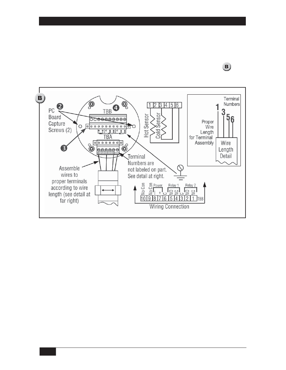
Remove the instrument enclosure lid by unscrewing in a counterclockwise direction.
Loosen the two, board-retaining captured screws.
Remove the printed circuit board by grasping the transformer on the center of the
board and, while rocking gently back and forth, pull firmly outward.
Connect power and alarm relay wiring to Terminal Block TBB as shown in .
Reinstall the switch electronics and tighten the retention screws.
Electrical Installation
NOTE: Connections to sensors are factory installed and should not be disconnected in the fi eld.
NOTE: For 24 VDC operation (factory prepared), connect +24 VDC to TBB7 and 24 VDC return to
TBB8. For 115 VAC or 230 VAC operation, there is no polarity.
NOTE: Connect ground wire to the ground screw located in back of instrument enclosure. A
ground wire must be attached to the ground screw located inside and on the back of
instrument head for proper operation.
- Adjustable Dead Band Explosion Proof Pressure Switch (4 pages)
- 805QS Pressure Switch-Transmitter (8 pages)
- 805PT Pressure Transmitter (12 pages)
- Big Hermet Explosion Proof, Hermetically Sealed, Pressure Switch (8 pages)
- Bourdon Tube Explosion Proof Pressure Switch (4 pages)
- Dual Hi-Lo Explosion Proof Sealed Pressure Switch (4 pages)
- Explosion Proof (8 pages)
- Explosion Proof (4 pages)
- Explosion Proof Pressure Switch UL/CSA/ATEX (8 pages)
- Mini-Hermet (8 pages)
- Mini-Hermet (4 pages)
- Sub Mini Hermet (4 pages)
- Omni Weatherproof Pressure Switch (4 pages)
- Weatherproof Pressure Switch (4 pages)
- Weatherproof Pressure Switch (2 pages)
- 805PT Pressure Transmitter (8 pages)
- 815DT Smart (24 pages)
- 815PT Smart Pressure Transmitter (24 pages)
- 534CR Pressure Transmitter (8 pages)
- 534HS Two-Wire Pressure Transmitters (12 pages)
- 536CR Low Power Pressure Transmitters (8 pages)
- 536HS Low Power Pressure Transmitters (8 pages)
- 510IM Immersible Transmitter (4 pages)
- 503FR Fixed Range Pressure Transmitter (4 pages)
- 101/121 Differential Pressure Switches (12 pages)
- Dual Opposed Diaphragm (12 pages)
- High Static Operation (8 pages)
- High Static Operation (12 pages)
- Low Pressure Switch Low Range Series 20 (8 pages)
- Low Range (4 pages)
- Single Diaphragm (4 pages)
- Big Hermet (12 pages)
- Direct or Remote Mount Explosion Proof UL/CSA/ATEX (8 pages)
- Side Mounted Level Switches (16 pages)
- Flanged Level Switches (4 pages)
- Sealed Level Switches (8 pages)
- 1510 Side Mounted Level Switch (8 pages)
- 1520 Electric Flow Switch (8 pages)
- 1530 Pneumatic Level Switch (4 pages)
- 1540 Side Mounted Non-Bleed Pneumatic Level Switch (4 pages)
- 1550 Top Mounted Level Switch (8 pages)
- 1710 Compact Level Switch (8 pages)
- Multi Point RF Level Switch (36 pages)
- Single Point RF Level Switch (12 pages)
- Single Point RF Level Switch (16 pages)