SOR Vertical Displacer Top Mounted Series Level Switch User Manual
Page 6
6/16
Form 425 (08.12) ©2012 SOR Inc.
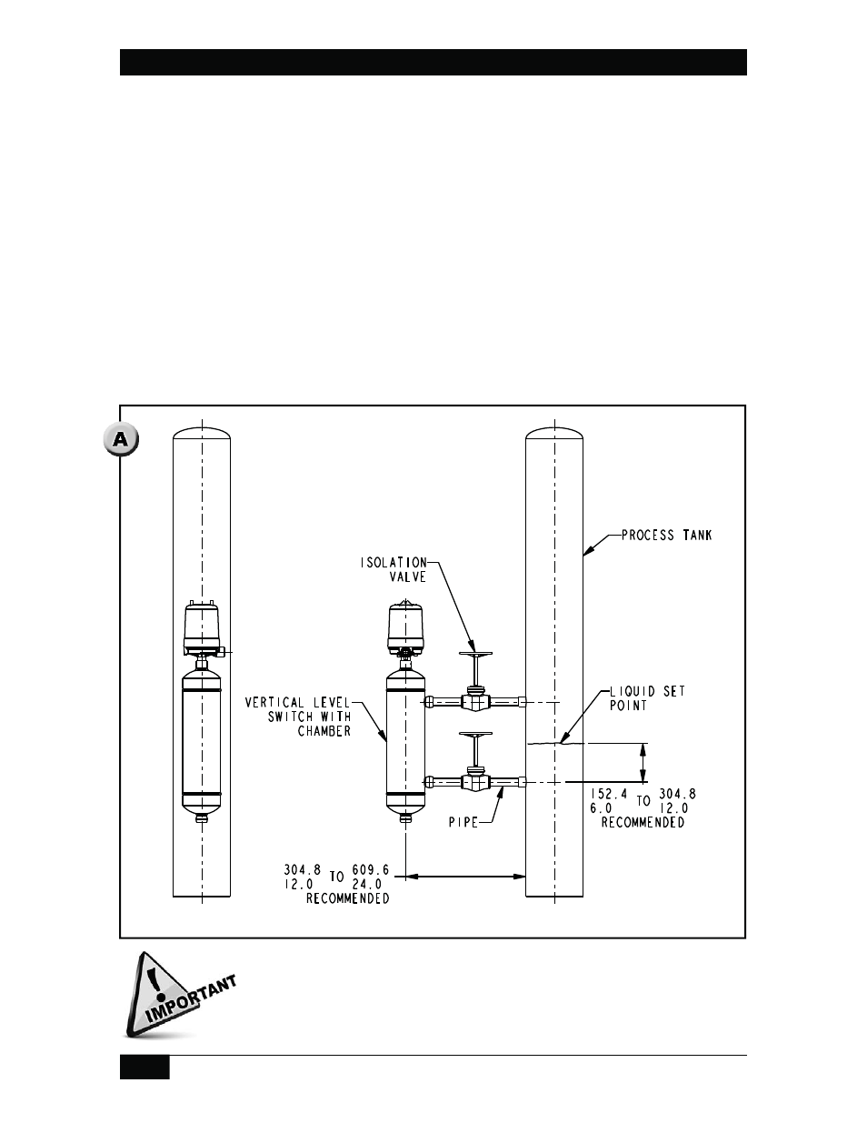
Locate switch chamber process connection 12” to 24” (300mm to 600mm) away
from the process pipe or tank.
Locate the switch chamber so that the switch actuates or deactuates at the desired
level. Refer to catalog for set point information.
For bottom chamber connections, connect the bottom chamber process connection
to the process pipe or tank 6” to 12” (150mm to 300mm) below the centerline of
the chamber. For side chamber connections, pipe directly to the process pipe or
tank. This will ensure liquid level in the switch chamber is as close as possible to
process liquid level.
Inside diameter of piping, including elbows, tees and valves, must be equal to or
greater than process connection diameter.
One elbow is recommended to connect the level switch chamber with the process
pipe or tank (if required).
Single Switch Chamber Installation
Drawing 0390737
Deviating from any of these instructions may adversely affect operation
of the level switch by restricting liquid fl ow into the switch chamber. The
recommended dimensions allow adequate space for isolation valves,
pipe fi ttings and insulation. Structural support (not shown) must be
provided for level switch chambers.