Wiring mechanism – SOR Vertical Displacer Top Mounted Series Level Switch User Manual
Page 10
10/16
Form 425 (08.12) ©2012 SOR Inc.
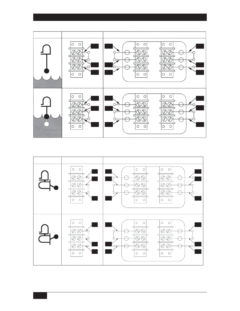
Wiring Mechanism
1
2
3
C
NO2
NC
C
C2
NO
NO2
NO
NC2
NC
NC2
C2
NO1
C1
NC1
NC1
NO1
C1
Float Position
SPDT Mechanism
DPDT Mechanism
SOR Control Devices
SOR Control Devices
4
5
6
1
2
3
4
6
1
2
3
1
2
3
5
SOR Control Devices
SOR Control Devices
Float Position
SPDT Mechanism
DPDT Mechanism
C
NC1
C1
NO1
NC1
C1
NO1
NC2
C2
NO2
NC2
C2
NO2
NC
C
NO
NC
C
NO
1
2
3
1
2
3
1
2
3
1
2
3
4
5
6
4
5
6
Vertical
Horizontal
NOTE: For C, G, R, S & Y Switch Assemblies, customer is to wire to the outside terminals.
This manual is related to the following products: