2 layout and mode of operation, 1 layout of the freeze-dryer, 1 functional and operating elements – Martin Christ Epsilon 2-10D LSCplus User Manual
Page 12
Freeze-dryer EPSILON 2-10D LSCplus
2 Layout and mode of operation
12
Version 04/2013, Rev. 1.5 of 16/12/2014 • sb
Translation of the original operating manual
Pos: 17 / 200 Christ /36 0 GT -BA La bor -Pilot (S TANDARDMODULE) /02 0 Aufb au u nd Wirk ungs weise/ 020 Aufb au u nd Wir kung sweise == === == == === == == === == == === = @ 25\ mod _14 049 832 3599 4_6 8.d ocx @ 1830 19 @ 1 @ 1
2 Layout and mode of operation
Pos: 18 / 200 Christ /36 0 GT -BA La bor -Pilot (S TANDARDMODULE) /02 0 Aufb au u nd Wirk ungs weise/ 020 -00 10 Au fba u de r Ge frie rtr ocknu ngsa nlag e-- --- -- --- -- --- -- --- --- -- --- -- --- --- -- --- -- --- -- - @ 2 5\m od_ 140 4983 236 941 _68 .docx @ 18 303 3 @ 2 @ 1
2.1 Layout of the freeze-dryer
Pos: 19 / 200 Christ /36 1 GT -BA La bor -Pilot (PROJEKTE )/Epsilon 2- 10D LSC plus Sta nda rd/0 20 Auf bau un d Wirku ngsweis e/02 0- 0010 -00 10 Fu nktio ns- und Be dien elem ente E2-1 0D @ 25\m od_ 140 498 487 913 4_6 8.docx @ 1 863 51 @ 3 @ 1
2.1.1 Functional and operating elements
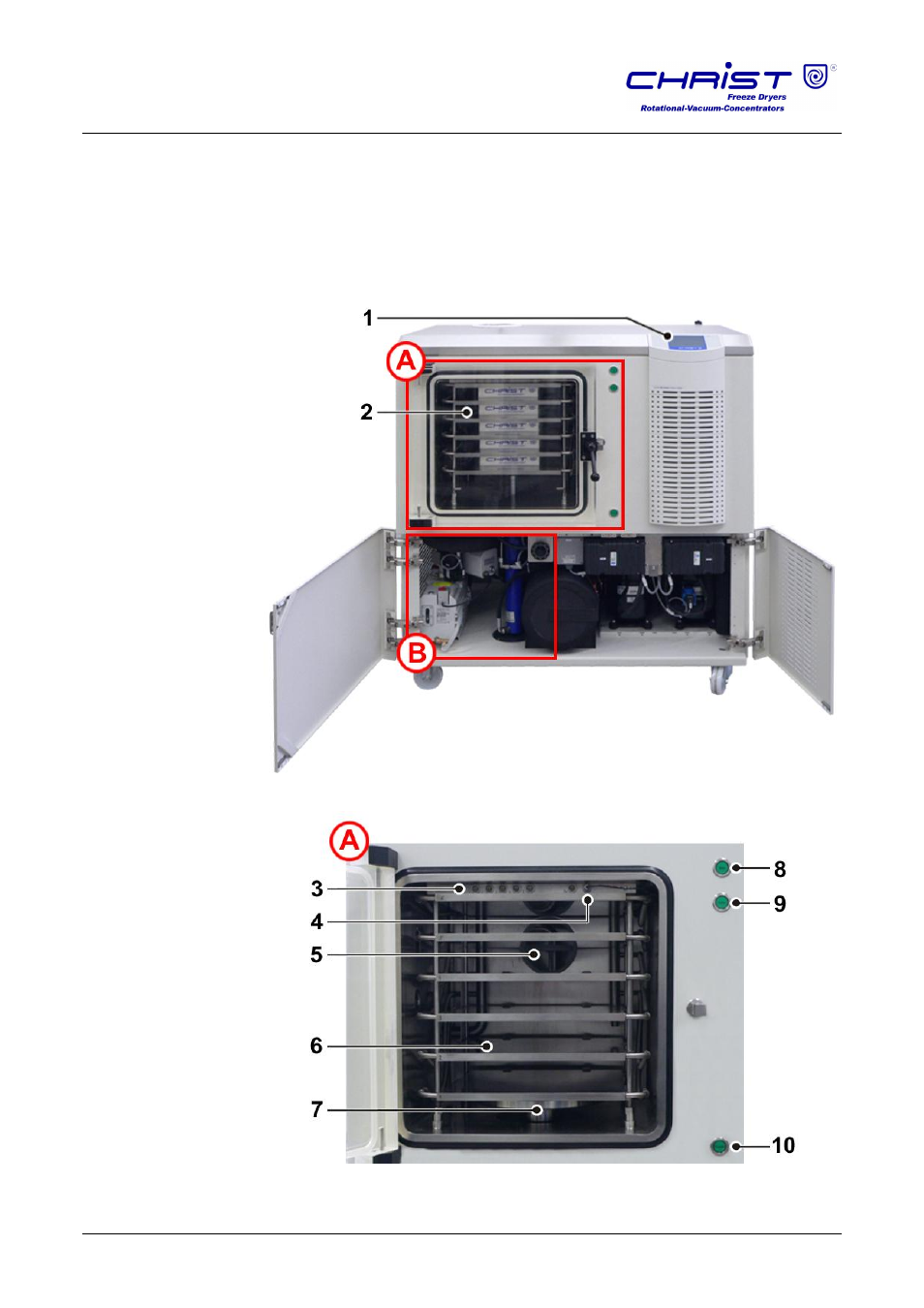
1
Control system
2
Drying chamber with
loading door
Fig. 1:
Front of the freeze-dryer
3
Connections for the
product sensors
4
Connection for the
intermediate valve
5
Intermediate valve
6
Shelves
7
Hydraulic dome with
bellows
8
Push-button "Up"
(hydraulic system)
9
Push-button "Down"
(hydraulic system)
10 Push-button
"Release” for two-
hand control of the
hydraulic system
Fig. 2:
Detailed view A – drying
chamber