N 6.10.3, Front panel interface 31 – Lab.gruppen LM 44 User Manual
Page 37
Front Panel Interface
31
Lake LM Series Operation Manual Rev 1.2.8
The Corner parameter is adjustable in 0.1 dB increments, subject to defined level limits. This figure repre-
sents the level below the limiter threshold at which compression commences; the larger this negative value,
the softer the knee. A setting of 0 dB implies a hard-knee characteristic.
LimiterMax provides peak and RMS limiting
features, referred to as MaxPeak and MaxRMS
respectively. Full details regarding LimiterMax can
be found in the Lake Controller Operation Manual.
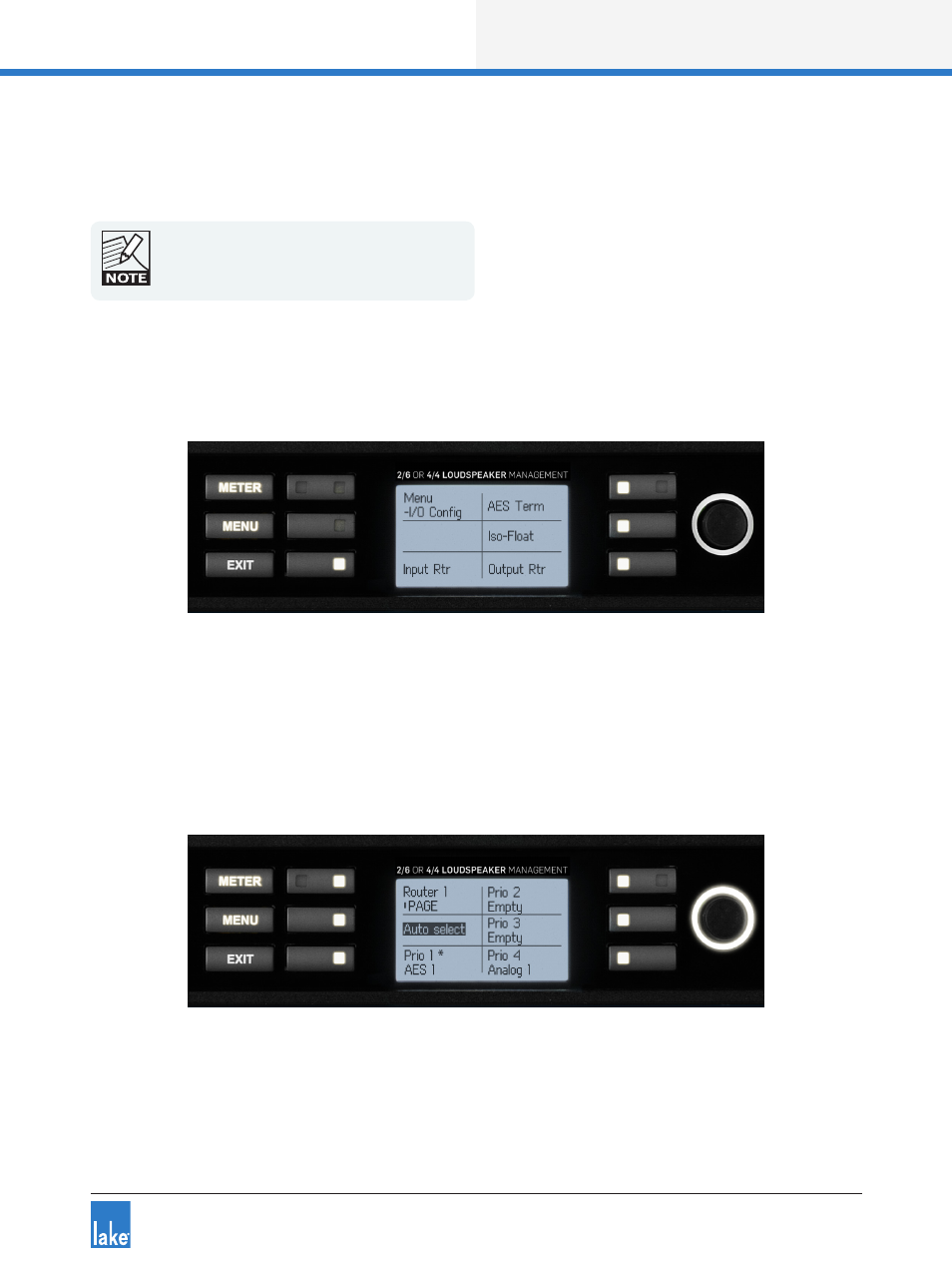
6.10.3 I/O Config Submenu
MENU > I/O CONFIG
Figure 6-16: I/O Config Submenu
This menu provides configuration options for input and output routing, along with settings for AES Termina-
tion and Iso-Float as described in the following sections.
6.10.3.1 Input Router
MENU > I/O CONFIG > INPUT RTR
Figure 6-17: Input Router 1
The signal flow diagrams in chapter 5 highlight that there are eight Input Routers available on LM Series
devices.