8 module i/o mute buttons and led meters, Front panel interface 21 – Lab.gruppen LM 44 User Manual
Page 27
Front Panel Interface
21
Lake LM Series Operation Manual Rev 1.2.8
In Menu Mode these buttons are used to navigate the menu structure. A white LED illuminates on each
button when a valid menu option is available.
6.8 Module I/O Mute Buttons and LED Meters
LM Series devices provide mute functions at several points in the audio signal path. Please refer to section
5.1 for mute locations and descriptions.
Three types of mute are available from the front panel:
1. Input Router Mutes
2. Module Input Mutes
3. Module Output Mutes
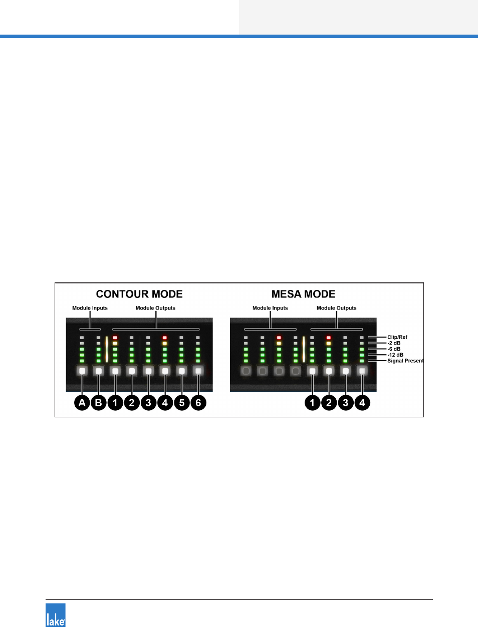
In Home View (default), Module Input and Output Mutes are controlled via the dedicated mute buttons
underneath each channel’s five-segment LED meter as shown in Figure 6-4.
Figure 6-4: Dedicated Module Input and Output Mutes - Home View
In Figure 6-4, the buttons labelled A & B provide Module input muting; the buttons labelled 1-6 provide
Module output muting.
The embedded LED in each mute button confirms whether the associated Module input/s or output/s are
muted (red), unmuted (white), associated input router is muted (pink), or unused (not illuminated) as shown
in Figure 6-5.
A pink LED indicates a partial mute caused by a mute on an Input Router used by the associated Input
Mixer. If all Input Routers used by an Input Mixer are muted the LED turns red to indicate a full mute; this
type of mute cannot be unmuted from Home View. Input router mutes are accessed via the I/O Status View
as described below, or via the Lake Controller Levels screen as described in the Lake Controller Operation
Manual.