20 front panel interface, 3 rotary encoder, 4 dynamic function buttons – Lab.gruppen LM 44 User Manual
Page 26
20
Front Panel Interface
Lake LM Series Operation Manual Rev 1.2.8
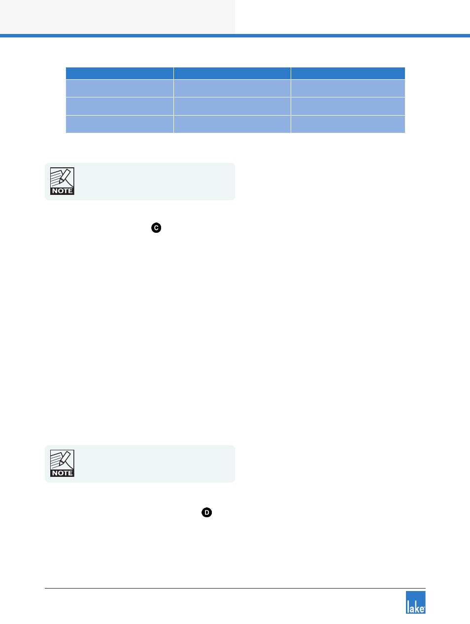
Warning Description
LCD Warning Text
Event Log Warning Text
Digital Clock Slipping
CLOCK SLIPPING
AES/Dante input clock slipping
Temperature Warning
TEMP WARNING
Temp Warning: DSP area
Controller Offline
CTRL OFFLINE
n/a
Table 6-2: Warnings (YELLOW FAULT / WARNING LED)
Module Input/Output mute status is indicated by
the dedicated mute button LEDs. Clipping is
indicated by the associated red meter segment.
Please refer to section 6.8 for further details.
6.7.3 Rotary Encoder
The rotary encoder is used to adjust parameters in conjunction with the selection made via the dynamic
function buttons and LCD menus. The ring around the rotary encoder illuminates when a selected parameter
is available for adjustment.
Turn the encoder clockwise to increase the selected parameter, or counter-clockwise to decrease the value.
Parameters with only two states (e.g. ON, OFF) are toggled by turning clockwise or counter-clockwise.
Some parameters enable simultaneous adjustment of a combination of input and output channels.
To select which channels are adjusted:
1. Press the associated soft button/s to select the parameter/s for editing.
A selected parameter is indicated by inverse text and background color.
2. Use the rotary encoder to change the value.
It is possible to select multiple parameters for simultaneous editing even if the values are different on each
channel. Turning the rotary encoder will adjust each parameter by the same increment. When in Meter
Mode, the rotary encoder allows the user to change between the available meter views.
Some menus permit parameters to be adjusted
across multiple channels simultaneously by default.
6.7.4 Dynamic Function Buttons
The buttons surrounding the display are unlabeled because their functions change according to the currently
selected menu or display.