N figure 6-5, 22 front panel interface – Lab.gruppen LM 44 User Manual
Page 28
22
Front Panel Interface
Lake LM Series Operation Manual Rev 1.2.8
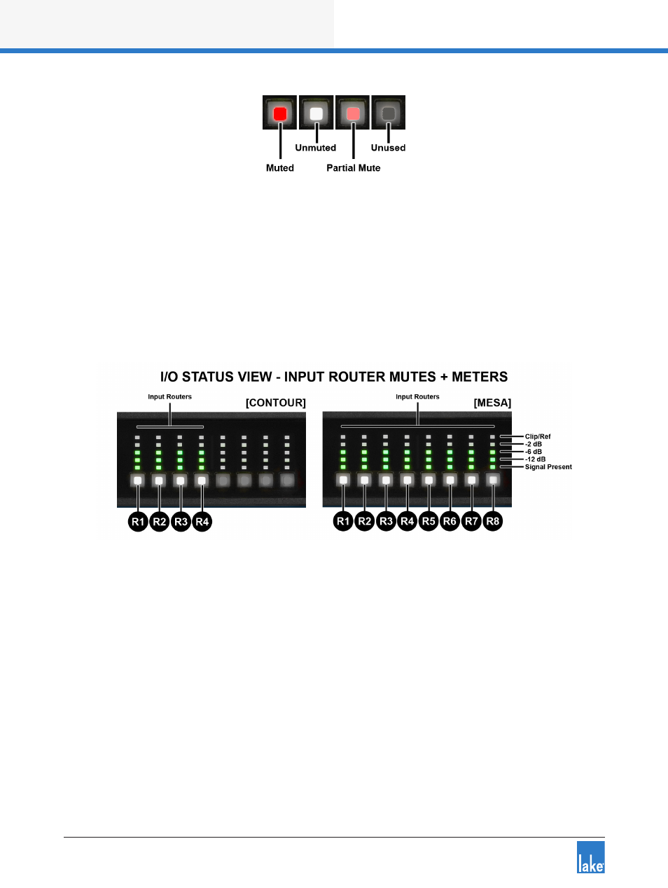
Figure 6-5: Mute Button LED Colours and States
In I/O Status View (accessed via the METER button as described in section 6.9.4) the front panel mute
buttons and meters change to show Input Router mutes and Input Router metering; the dynamic I/O divider
line is not present and the buttons and meters change to represent the input router mute status and associ-
ated metering.
The number of Input Routers varies depending on the whether the frame is configured as Contour or Mesa
as shown in Figure 6-6; the number and location of the Input Router channels is identified by the labels
R1-R8.
Figure 6-6: I/O Status View - Input Router Mutes and Meters
The Input Router Mutes can also be viewed and changed via buttons adjacent to each label the front panel
I/O Status view.
6.8.1 Module Input and Output Mutes
In Home View, dedicated mute buttons are provided for the Module inputs and Module outputs. To mute
or unmute a module input or output, tap the corresponding button. The button illuminates as described in
section 6.8 and shown in Figure 6-5.
Module input mutes are only available in Contour Mode; Module input mutes are not applicable in Mesa
Mode. The quantity and position of the output mute buttons changes as shown in Figure 6-4 depending on
whether the device is configured in Contour Mode (six outputs) or Mesa Mode (four outputs).
Please refer to the Lake Controller Operation Manual for details of Module mute controls via the software.