Front panel interface 19, 1 communication led, 2 faults and warnings led – Lab.gruppen LM 44 User Manual
Page 25
Front Panel Interface
19
Lake LM Series Operation Manual Rev 1.2.8
6.7.1
Communication LED
This bright white LED signifies selection in the Lake Controller, or Controller communication providing visual
confirmation of:
1. Network communication between the Lake Controller and the Lake Processor (Flashing LED).
2. Selection of the Lake Processor in the Lake Controller software (Steady LED).
The Communication LED can be dimmed via the
front panel by selecting Frame menu, and then
Front - Dimming.
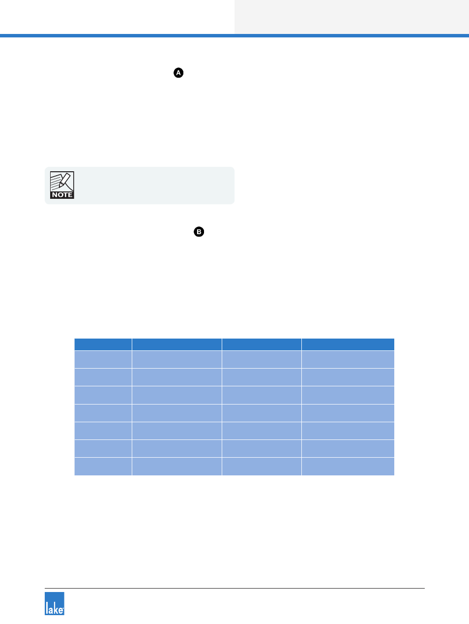
6.7.2 Faults and Warnings LED
This LED turns red to indicate a fault or mute state and turns yellow to indicate a warning. Additional clari-
fication of the fault or warning is displayed in the LCD. All mute, fault and warning states displayed on the
front panel are summarized in section 8.1.
Additional faults and warnings are reported in the Event Log of the Lake Controller only. All faults and
warnings recorded in the Event Log are listed in section 8.1 along with scenarios that may have arisen to
cause them.
Device
Fault / Mute Description
LCD Warning Text
Event Log Warning Text
LM 44 Only
A/D PSU Fault
PSU FAULT
Frame Fault: PSU
All LM Series
Protective Mute State
PROTECTIVE MUTE
Protective mute via GPIO
All LM Series
Overtemperature
OVERTEMP
Temp Fault: DSP area
All LM Series
No Input Source Available NO INPUT
No Input Source
All LM Series
Analog Input Fault
ANALOG IN FAULT
Frame Fault: Analog input
All LM Series
Fan Alarm
FAN FAULT
Frame Fault: Fan error
All LM Series
Input Router Mute
INPUT RTR MUTE
Input Router x mute
Table 6-1: Faults (RED FAULT / WARNING LED)