Installation instructions, Led light, Mounting the ilb-1826 – IOTA ILB-1826 User Manual
Page 2: Wiring, Installing the charge indicator, Installing the test switch, Illustration 1: recessed troffer fixture, Illustration 2 : strip fixture
Page 2
INSTALLATION INSTRUCTIONS
CAUTION: Before installing, make certain the A.C. power is off and the
ILB-1826 unit connector is disconnected.
1. LED LIghT
The
ILB-1826 is designed for use with LED arrays that operate up to 24 Watts.
2. mOUNTINg ThE ILB-1826
Remove the ballast/driver channel cover. mount the
ILB-1826 in the ballast/driver channel at least ½
″ away from
the LED driver. The
ILB-1826 may also be mounted on top of the fixture. The optional top mounting kit (Catalog
No. TmK-32) may be ordered separately from Customer Service.
When the
ILB-1826 is remote mounted, consult Customer Service for the maximum allowable distance between
the
ILB-1826 and the LED load. The maximum allowable distance of the ILB-1826 battery from the ILB-1826
electronics is 2 feet.
NOTE: The ILB-1826 is suitable for use in cold-weather applications only when connected to a cold-weath-
er battery pack.
3. WIRINg
Refer to the wiring diagram on the back page for the appropriate wiring of the LED array and driver. Install in
accordance with the National Electrical Code and local regulations. For additional wiring diagrams consult Cus-
tomer Service.
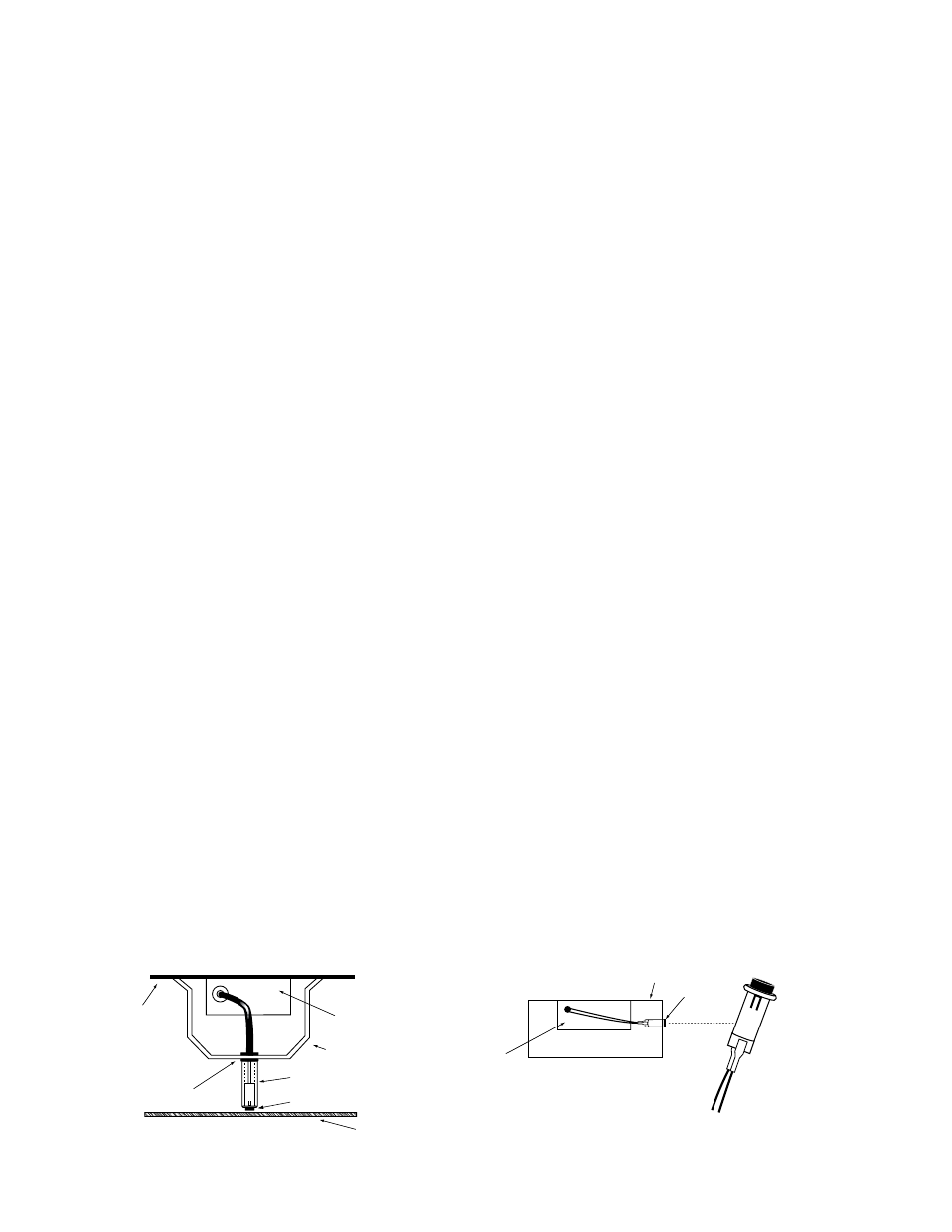
4. INSTALLINg ThE ChARgE INDICATOR
Recessed Fixture – Select a convenient location with proper clearance in the ballast/driver channel or ac-
cess cover and drill or punch a
7
/
8
″ hole (½″ knockout). Insert the
7
/8
″ bushing into the hole. Push the plastic tube
through the bushing. Disconnect the leads from the
Charge Indicator housing and route the leads down the
plastic tube. Reconnect the leads to the housing, observing the proper polarity (Red/Black or Red lead w/connec-
tor to positive (+) red tab). Push the entire assembly back into the tube until the lens collar rests against the plastic
tube. The plastic tube should be adjusted so that the
Charge Indicator is within ¼
″ of the fixture lens. The Charge
Indicator must be visible after installation. Refer to Illustration 1.
Strip Fixture – Select a convenient location on the side of the fixture so the
Charge Indicator can be seen
after installation. Allow for proper clearance inside the fixture and drill or punch a ½
″ hole. Disconnect the leads
from the
Charge Indicator housing. Push the Charge Indicator housing into the ½
″ hole until it is firmly locked in
place. Reconnect the leads, observing proper polarity (Red/Black or Red lead w/connector to positive (+) red tab).
Refer to Illustration 2.
5. INSTALLINg ThE TEST SWITCh
The
Test Switch should be mounted on the ballast/driver channel cover of a recessed troffer, or on the side of a
strip fixture, preferably adjacent to the
Charge Indicator. Drill or punch a ½
″ mounting hole.
7/8" BUSHING
FIXTURE
BALLAST CHANNEL COVER
PLASTIC TUBE
CHARGE INDICATOR
LIGHT
FIXTURE LENS
Illustration 1: Recessed Troffer Fixture
FIXTURE
CHARGE
INDICATOR
LIGHT
+ RED/BLK
OR RED LEAD
WHITE/RED
LEAD
+ RED
Illustration 2 : Strip Fixture
ILB-1826
OBSERVE PROPER POLARITy
ILB-1826
BALLAST/DRIVER
ChANNEL COVER