Installation instructions, Fixture, Mounting the ilb – IOTA ILB-SL-CP12 User Manual
Page 2: Wiring, Installing the threaded body test switch (tbts), Illustration 1, Illustration 2
Page 2
INSTALLATION INSTRUCTIONS
CAUTION: Before installing, make certain the A.C. power is off and the ILB-SL-CP
unit connector is disconnected.
1. FIXTURE
The
ILB-SL-CP can be used with most LED loads that operate at 10-60 VDC. See the ILB Model Specification
Chart for output specifications of the unit being installed.
1. The ILB-SL-CP series has been evaluated to and found compliant to UL standard 924. The as-installed
performance of system must meet or exceed all Federal, State, and Local code requirements.
2. Refer to Addendum 11042014 for detailed specifications and methods to calculate emergency light levels.
2. MOUNTING THE ILB
Mount the
ILB-SL-CP in the driver/lamp compartment or enclosed wireway so the wire leads are not exposed, at
least ½
″
away from the driver. Refer to Illustration 1
and 2.
When battery packs are remote mounted, consult Customer Service for the maximum allowable distance between
the battery pack and the load.
3. WIRING
Refer to the wiring diagram on the back page for the appropriate wiring of the LED load and driver. Install in ac-
cordance with the National Electrical Code and local regulations. For additional wiring diagrams consult Cus-
tomer Service.
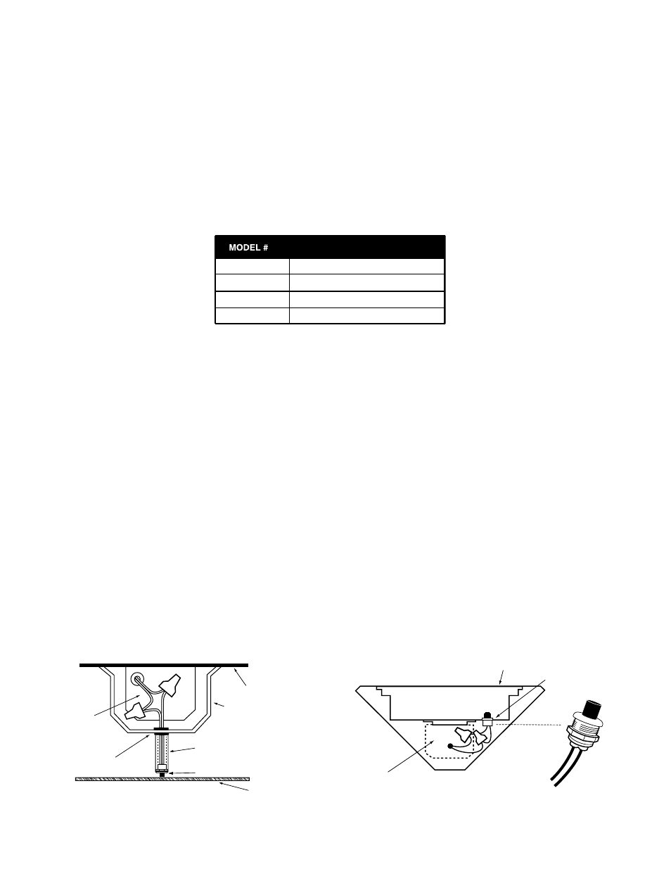
4. INSTALLING THE THREADED BODY TEST SWITCH (TBTS)
Recessed Troffer Fixture– Select a convenient location with proper clearance in the channel cover and drill or
punch a
7
/
8
″ hole (
1
/
2
″ knockout). Insert the
7
/
8
″ bushing into the hole. Push the plastic tube through the bushing.
Route the leads of the
TBTS through the plastic tube. Connect the LED wires from the unit to the TBTS (Red/
Black or Red w/tag to Red, White/Red to White). Push the entire assembly back into the tube until the lens collar
rests against the plastic tube. The plastic tube should be adjusted so that the
TBTS is within ¼
″ of the fixture lens.
The
TBTS must be visible after installation. Refer to Illustration 1.
Illustration 1
NOTE: Position the
TBTS so that
it can be seen after installation.
Illustration 2
+ RED
LEAD
WHITE
LEAD
FIXTURE
TBTS
7/8" BUSHING
FIXTURE
CHANNEL COVER
PLASTIC TUBE
TBTS
FIXTURE LENS
ILB-SL-CP
ILB-SL-CP
OBSERVE PROPER POLARITY
ILB-CP05
ILB-CP07
ILB-CP10
5 WATTS
7 WATTS
10 WATTS
ILB MODEL SPECIFICATION CHART
OUTPUT POWER (CONSTANT)
ILB-CP12
12 WATTS